
Additive manufacturing has a wide array of applications, such as creating custom medical devices, aerospace components, and artwork. With the list of potential uses continuing to grow, it’s important that this type of manufacturing can keep up with the demand. However, analyzing and optimizing this complex process can be difficult. What can engineers do to overcome this challenge?
The Versatility of Additive Manufacturing
Additive manufacturing is the process of creating a 3D object by adding one or more materials on top of each other layer by layer. To learn more about this type of manufacturing, we reached out to Professor Frédéric Roger of the Mines Telecom Institute, Lille-Douai Center. (IMT is a French public institution dedicated to higher education, research, and innovation in engineering and digital technologies.)
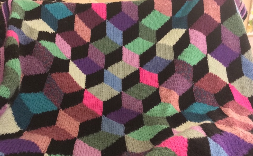
Professor Roger says that, in a sense, additive manufacturing is a bit like sewing or weaving. In both processes, a heterogeneous finished product is created by controlling how different raw materials are consolidated. In weaving, the materials are usually thread and yarn; however, additive manufacturing can use many materials, including polymers, metal alloys, ceramics, and composites.
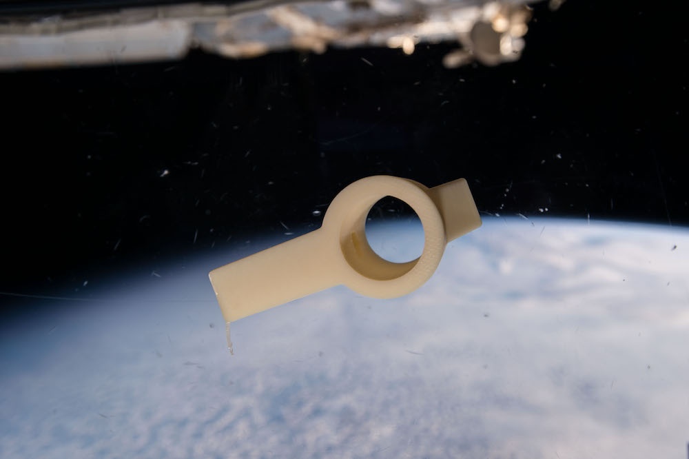
Choosing the right materials is important for creating an ideal finished product, be it a warm blanket (left, woven by my grandmother) or a customized aerospace part (right). Right image in the public domain in the United States, via Wikimedia Commons.
This wide range of materials means that additive manufacturing can be used to design a large amount of unique objects across many industries. For instance, Roger mentions that by using the right materials and thermodynamic conditions, engineers can make objects that withstand or adapt to severe environmental conditions. Such objects could even adapt to certain temperatures or chemical conditions by changing their shape or releasing chemical species (like drugs) that are trapped in a matrix. A transformation over time would add another dimension to the printed part, resulting in “4D printing”.
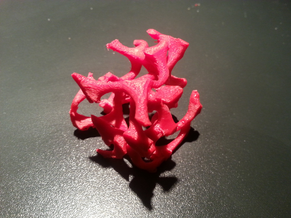
Sometimes, additive manufacturing parts are inspired by natural forms, like the bio-inspired example pictured here. Image courtesy Frédéric Roger.
According to Roger, the many opportunities that come with additive manufacturing make it “an unavoidable manufacturing process,” as it “offers new opportunities to develop optimized structures with advanced materials.” However, before engineers can create these structures, they have to improve the additive manufacturing process.
Solving the Challenges of Simulating Additive Manufacturing
Since additive manufacturing is a complex process, it can be difficult to study. This technique varies based on the materials involved and the specific type of additive manufacturing. Studying this process also requires accounting for many different effects, such as:
- Multiple phase transformations
- Transfer of energy, mass, and momentum
- Sintering
- Photopolymerization
- Drying
- Crystallization
- Deformation
- Stress
To account for these factors, engineers can use the COMSOL Multiphysics® software, which Roger mentions is “a unique software that has great advantages in the simulation of additive manufacturing.” The software helps engineers to not only “optimize the additive manufacturing process but also to predict the mechanical and microstructural consequences on the product.” Through this, engineers can include all of the relevant physics and determine the ideal manufacturing conditions and part geometries that balance the needs of stiffness, weight reduction, and heat dissipation.
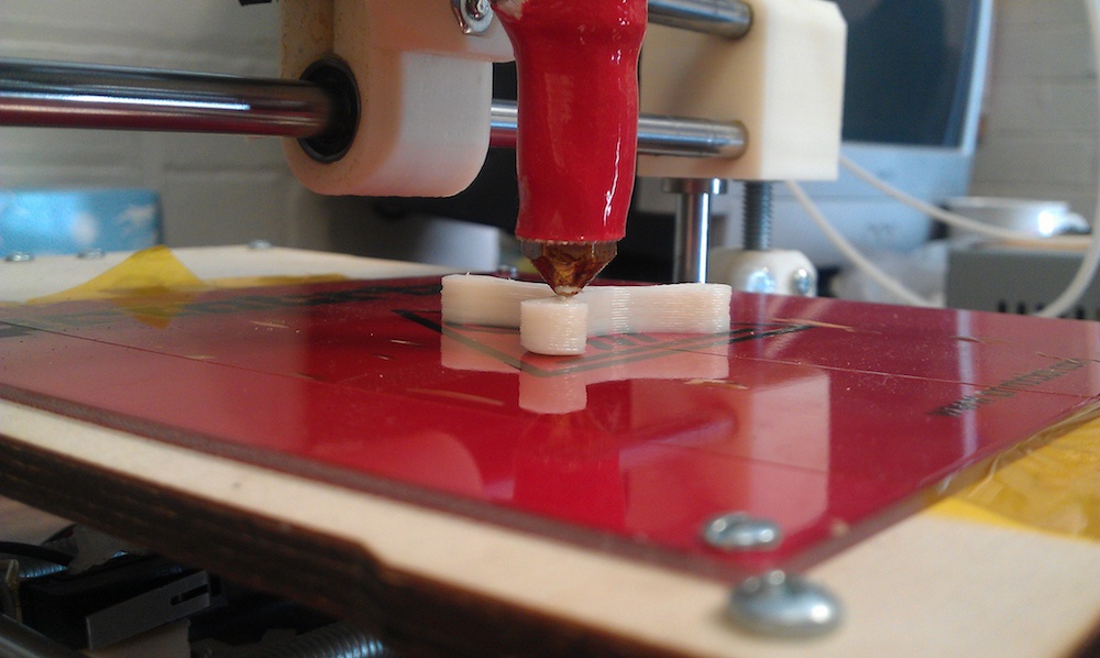
Left: An example of the additive manufacturing process, which involves many different physics. Image by Les Pounder — Own work. Licensed under CC BY-SA 2.0, via Flickr Creative Commons. Right: Example of an additive manufacturing part created with two materials and filled with a honeycomb inner structure. Image courtesy Frédéric Roger.
A challenge is that analyzing the additive manufacturing process while coupling the relevant physics can result in large model sizes and long computational times. To overcome this issue, Roger implements several different simulation strategies, such as activating mesh properties, using adaptive remeshing, and performing sequential simulations.
By taking a sequential approach, Roger is able to better analyze the succession of thermodynamic states that a material experiences during additive manufacturing. At the same time, this approach helps to reduce the complexity of the multiphysics couplings by dissociating them over time. As such, sequential simulations provide a way to comprehensively model and optimize the additive manufacturing process while reducing computational costs.
Optimizing an Additive Manufacturing Part with Multiphysics Simulation
For their simulations, Roger and his team focused on fused-deposition modeling (FDM®), a common additive manufacturing technique that is both affordable and enables control over process parameters. The aim of the study was to optimize the internal and external geometry of a printed thermoplastic part and achieve the best possible performance. To accomplish these goals in an efficient manner, the team split their analysis into three parts, discussed below.
For more information about this study, check out the researchers’ paper.
Part 1: Topological Optimization of the External Part Geometry
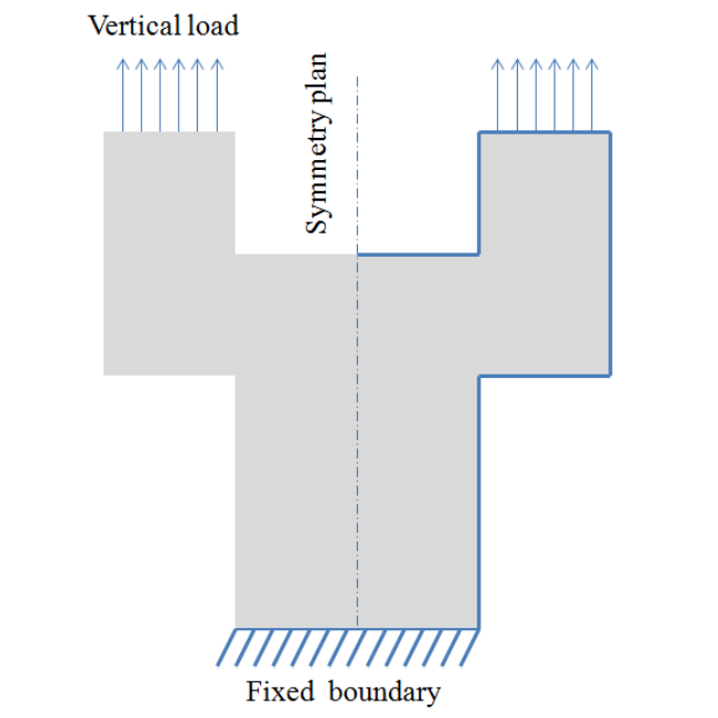
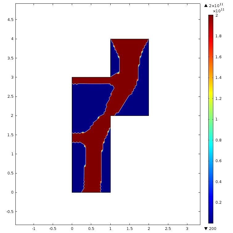
In the first part of the study, the researchers wanted to minimize the total weight of a printed structure while maintaining a material distribution that maximizes stiffness. To do so, they used topological optimization and structural mechanics analysis to study a mechanical structure exposed to a tensile load.
Original geometry and boundary conditions (left) and the Young’s modulus distribution that defines the optimal shape by color contrast (right). Left image by F. Roger and P. Krawczak and taken from their COMSOL Conference 2015 Grenoble presentation. Right image courtesy Frédéric Roger.
Through the studies, they found an optimal shape for the part, determining that the middle of the shape has the highest stress levels. As such, the researchers divided the structure into domains based on the stress concentration field: a high-stress middle area surrounded by two low-stress areas. In the following study, they used this information to apply specific manufacturing conditions to the high-stress zone
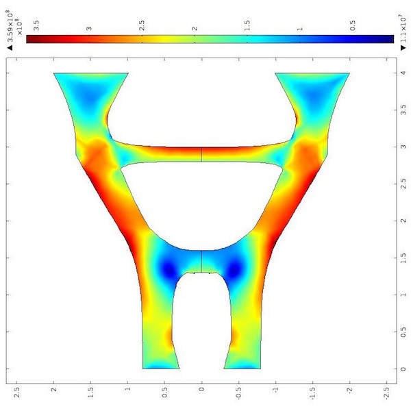
The stress fields in the optimized geometry. Image courtesy Frédéric Roger.
Part 2: Comparing Infill Strategies for an Optimized 3D Part
In the second study, the researchers aimed to increase the stability of the high-stress zone in their part by testing two possible infill strategies:
- Heterogeneous filling with variable densities
- Multimaterial filling
In the heterogeneous case, the team created a more resistant domain in the high-stress middle area by using a higher density of infill. At the same time, they minimized the weight of the external areas by using less material. The results indicated that the ideal geometry contains 60% material in the high-stress region and 20% material in the low-stress regions.
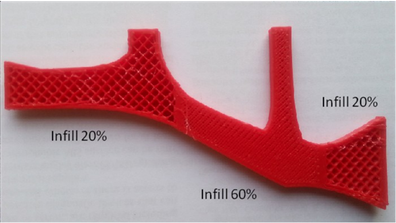
Printing an optimized part using one material with varying densities. Image by F. Roger and P. Krawczak and taken from their COMSOL Conference 2015 Grenoble paper.
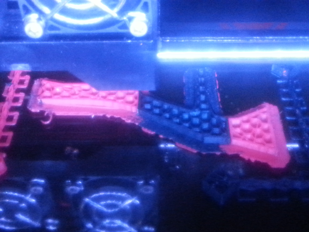
As shown below, the multimaterial case involved using red ABS plastic on the ends of the part and black conductive ABS with improved mechanical properties in the middle. The team found that they could replace the conductive ABS with materials similar to ABS that have reinforced filters to increase stiffness.
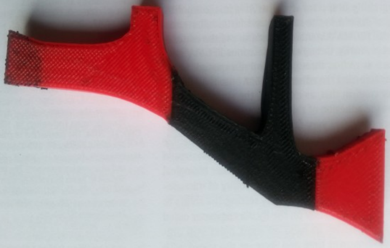
Printing an optimized part using two materials. Image by F. Roger and P. Krawczak and taken from their COMSOL Conference 2015 Grenoble paper.
Part 3: Heat Transfer Analysis of Fused Thermoplastics Deposition
After optimizing the inner and outer designs of the 3D-printed part, the researchers modeled the fused thermoplastic deposition process and evaluated manufacturing parameters. The resulting simulations helped them to accurately predict thermal history, wetting conditions, polymer crystallization, interactions between filaments, and residual stresses and strains. One example is shown below, depicting the plastic strain during the heating and cooling process.
The fusion and solidification of a disk that is irradiated by a laser beam as well as the resulting plastic strain evolution. This analysis takes Newtonian fluid flow and solid thermomechanical properties into account. Animation courtesy Frédéric Roger.
The study also investigated the heat and mass transfer within the first two layers of a thin-walled tube. The researchers were then able to analyze the plastic droplet deposition process and identify areas where the filaments reached fusion temperature. The animations of the material deposition study are shown below. They depict a heat source moving along a deposition pattern and heating the filaments up to fusion temperature, ~230°C for ABS droplets. The extruder path domain in the simulations is premeshed and the meshes are continuously activated depending on the extruder’s position.
Two-layer circular deposition (top). The moving heat source represents the hot ABS deposition. The thermal expansion of the two layers (amplified by a factor of five), showing the moving heat source activating the properties of the material (bottom). Here, blue indicates a nonactivated mesh and the physical properties (thermal conductivity and stiffness) are close to zero. Animations courtesy Frédéric Roger.
Using these simulations, Roger and his team predicted the temperature field between the filaments during the deposition process, an important factor that affects filament adhesion. Similar analyses could help researchers compare different additive manufacturing conditions and determine the best deposition strategy for a specific application.
Concluding Remarks on Simulating Additive Manufacturing
Roger says that these simulations enabled his team to “define an additive manufacturing part whose internal and external architectures give it the best possible industrial performance.” Of course, this is only the start of what can be achieved by combining additive manufacturing and multiphysics simulation.
If you have any tips for using COMSOL Multiphysics to study the additive manufacturing process, be sure to let us know in the comments below!
Learn More About Additive Manufacturing and 3D Printing
- Read more about the researchers’ work in their paper: “Optimal Design Of Fused Deposition Modeling Structures Using Comsol Multiphysics“
- Check out these related blog posts:
FDM is a registered trademark of Stratasys, Inc.




Comments (0)