
Aircraft rely on landing gear in order to taxi, take off, and land. The landing gear of your average commercial airplane consists of a shock-absorber cylinder and piston, and a pair of tires. Intuitively, the shock-absorber experiences stresses as the landing gear touches the ground — but how much? In order to design a landing gear mechanism that can withstand many landings, and to determine when it’s time to swap out an old one, we can perform a multibody dynamics analysis. We may also want to look at the heat generation and distribution in the shock-absorber assembly, as it is sure to heat up.
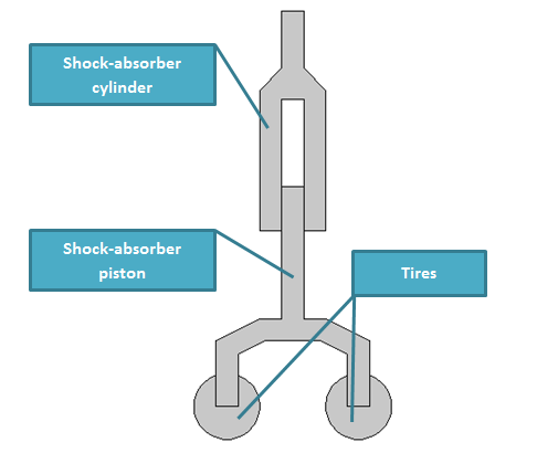
Shock-absorber assembly of aircraft landing gear mechanism.
Multibody Dynamics Analysis of Aircraft Landing Gear
Let’s assume we want to analyze the shock-absorber of aircraft landing gear as represented by the geometry shown above. As you can see, it’s comprised of three main parts: a shock-absorber cylinder, a shock-absorber piston, and a couple of tires. These components are essential to our analysis, but anything else is not, and will thereby not be modeled.
The cylinder and piston in our landing gear example are connected via a prismatic joint — one of the joints mentioned by my colleague Pawan in his blog entry on simulating mechanical systems. The joint has only one translational degree of freedom. In order to ensure passengers are comfortable and the landing gear intact when the plane lands, the joint contains a spring and damper that together absorb the ensuing shock during touch-down. The Prismatic Joint feature in the Multibody Dynamics Module comes with a “spring and damper” subfeature, which we’ll use in this case. The tires, of course, also play a part in the landing scenario. Their effect can be modeled using the Spring Foundation feature on the bottom surfaces of the shock-absorber piston.
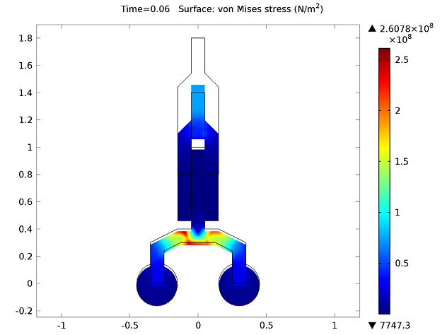
By plotting the von Mises stress distribution in our mechanical system, we can see that when the shock-absorber cylinder is at its most displaced position, the stress is at a maximum in the shock-absorber piston. The stress profile shows that the maximum value of stress is near the center of the shock-absorber piston (the red and yellow zones in the surface plot).
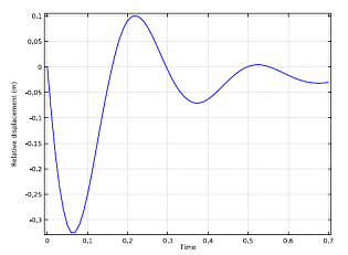
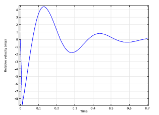
We can also have a look at the relative displacement and relative velocity between the two shock-absorber components as they occur during landing:
|
|
| Relative displacement between the cylinder and piston. | Relative velocity between the cylinder and piston. |
As you can see, the amplitude of the relative displacement starts off very high, but then decays very quickly as the energy is lost in the shock-absorber and the set of tires. The relative velocity plot paints a similar picture for the same reason.
During the landing of an aircraft, the kinetic energy of aircraft associated with the vertical motion converts into various forms of energy. We can plot different forms of energy to learn more about them.
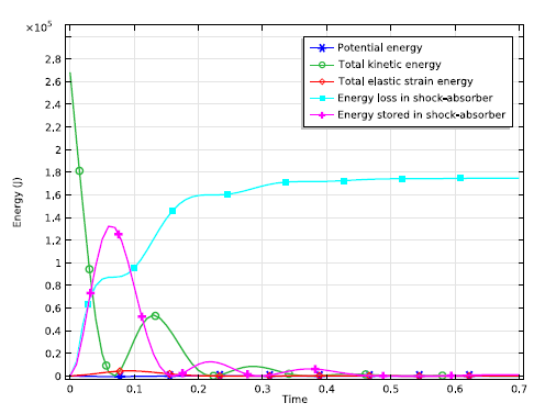
Different forms of energy in the landing gear mechanism.
As you can imagine, the kinetic energy is initially very high, but declines to zero due to energy dissipation in the shock-absorber assembly in the rest of the cycles. The dissipation further explains why the other energy forms are so low.
Heat Transfer Analysis of a Shock-absorber
As I mentioned, the shock-absorber parts will heat up due to energy dissipation in the damper. Now that we have set up and modeled the stresses in our system, we can couple our model with the Heat Transfer in Solids interface. Doing so will enable us to calculate the rise in temperature in various components. According to the visualization below, the temperature is highest around the piston-cylinder boundaries.
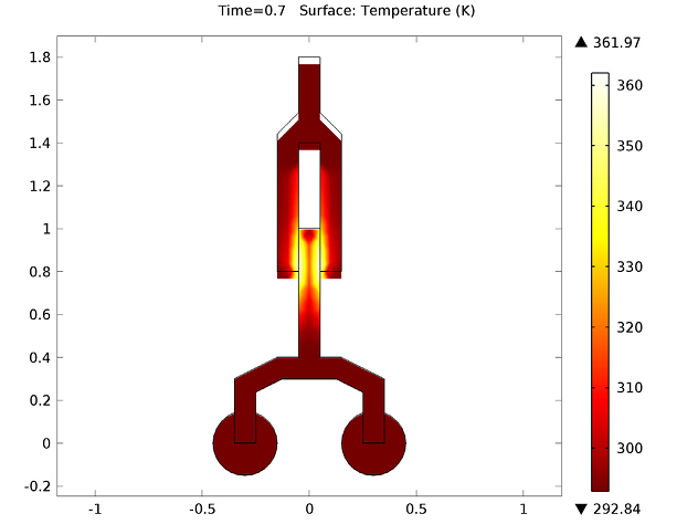
The landing gear’s temperature profile.


Comments (0)