
Have you ever noticed that being around a happy, enthusiastic friend makes you feel happy too? You can look at mutual induction in a similar way: A current flowing through one circuit creates a current in a nearby circuit. Mutual inductance measures the amount of change required for this effect to take place. Here, we explore using simulation to compute the mutual inductance in different wire coil arrangements.
Mutual Inductance and Induced Currents
When a time-varying current flows through an electrical circuit, the primary circuit or primary coil, it creates a changing magnetic field. The magnetic field changes with time and induces a current in another nearby coil, the secondary coil. This effect is called mutual induction. Mutual induction is important in the operation of transformers, motors, generators, and other devices.
Oftentimes, you may want to find out how much change is needed in the primary coil’s current to create a specific voltage in the secondary coil. To do so, you can find the mutual inductance by calculating the effect on one coil due to changes in the other coil. Computing the mutual inductance can also help to avoid any mishaps in a device, as mutual induction can cause unwanted coupling between conductors.
When computing mutual inductance, the orientation, the winding pattern, and the placement of the coils in relation to one another are all important factors. If two coils are close together, nearly all of the magnetic flux generated by the primary coil will interact with the turns of the secondary coil, thus creating a large mutual inductance. On the other hand, coils that are spaced far apart from each other will have a much smaller mutual inductance. The presence of a magnetic material can also increase mutual inductance.
Let’s take a closer look at how these factors affect mutual inductance by simulating a few different coil arrangements.
Using Simulation to Compute Mutual Inductance
Between Single-Turn Coils
For our single-turn coil example, the primary circuit is a single-turn coil with a radius of 100 mm and the secondary coil is a single-turn coil with a radius of 10 mm. Both wires are 1 mm thick and exist in a concentric coplanar arrangement, modeled in 2D axisymmetry. The domain is surrounded by a region of infinite elements. The primary coil is excited with a current of 1 A at a frequency of 1 kHz.
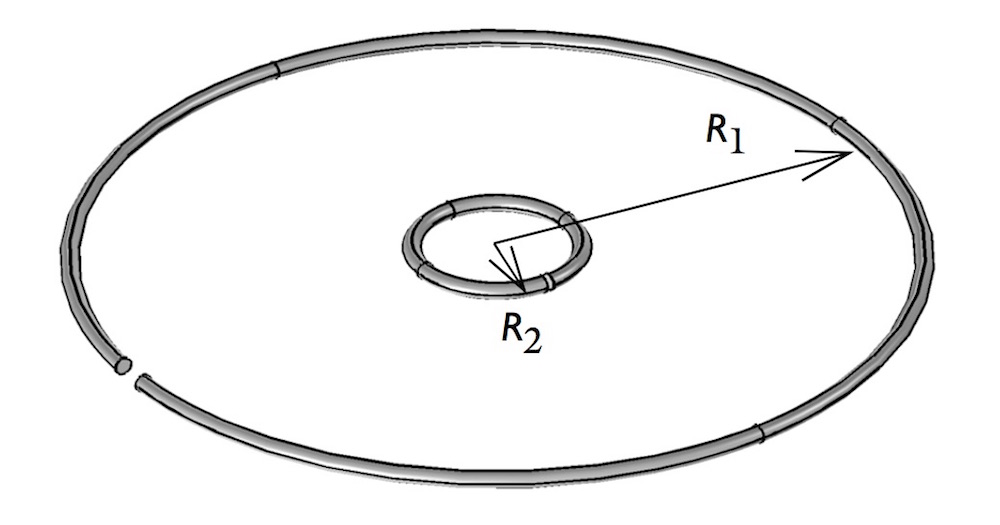
An arrangement of two single-turn coils.
The Single-Turn Coil feature is used to model the coil arrangement in a DC state. Since the current in the primary coil is constant (DC), it cannot create a changing magnetic field. Thus, the magnetic flux through the secondary coil won’t change, meaning that no voltage is induced. However, you can still calculate the mutual inductance by analyzing the total magnetic flux and comparing it with analytic results. The arrangement is then modeled in an AC state to compute the induced currents in the secondary coil.
The simulation results show a plot of the DC magnetic field as well as the computed mutual inductance of the coil arrangement.
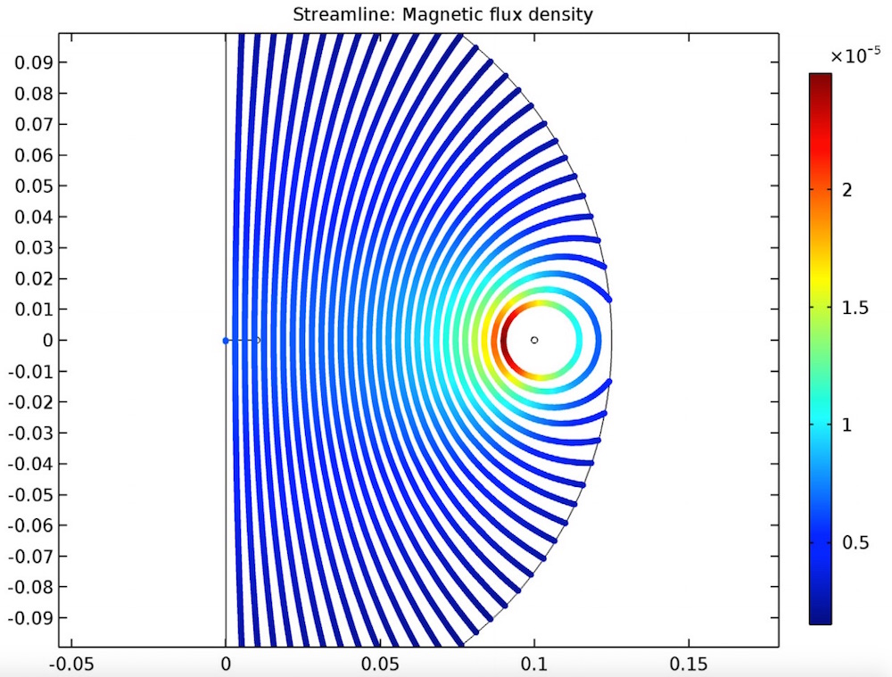
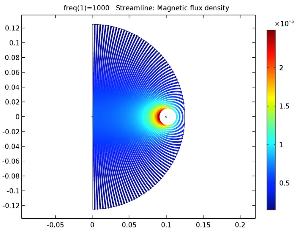
The magnetic flux density for the DC model is plotted.
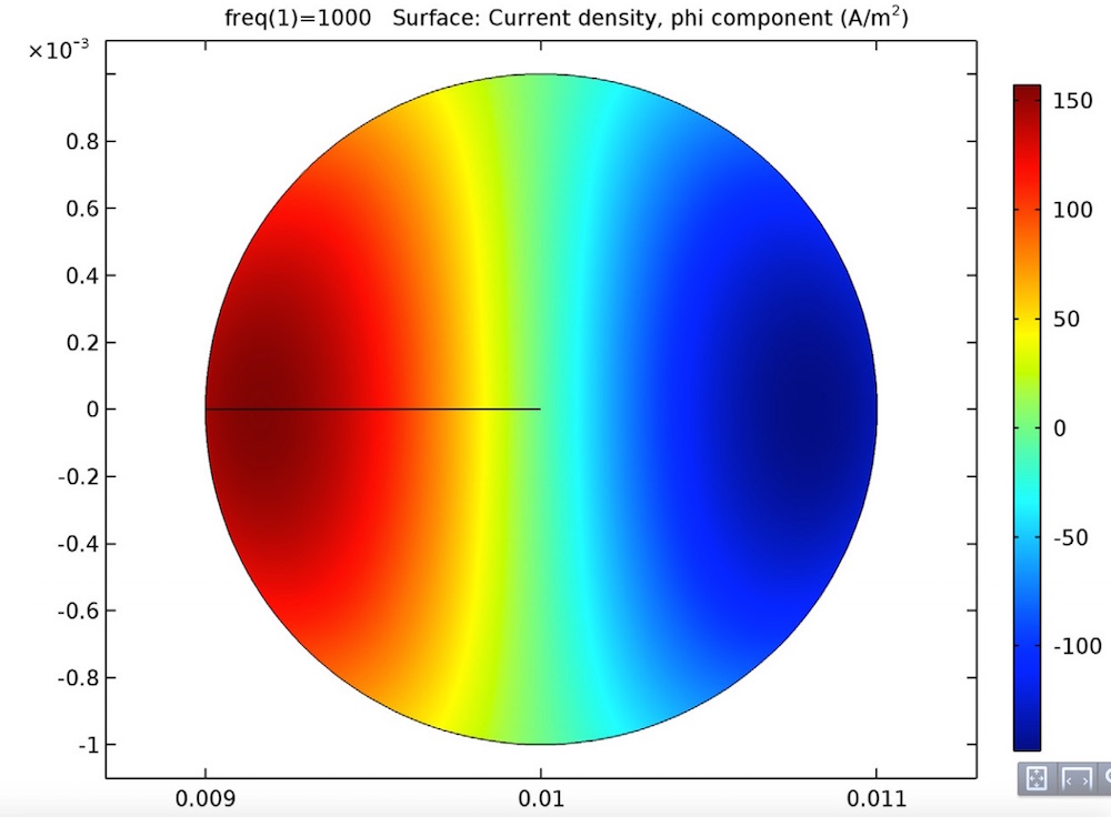
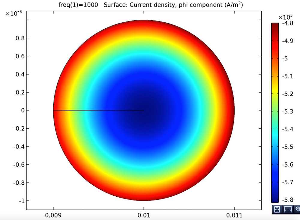
The induced currents of the single-turn coil arrangement in an open circuit (left) and a closed circuit (right).
From the results, you can analyze the relationship between the induced currents of the AC model and the inductance of the DC model.
In a Multi-Turn Coil and a Coil Group
A similar coil arrangement can be modeled with two different variations. In this example, the primary circuit is the same single-turn coil, but the secondary coil is a twenty-turn coil. We can compute the mutual inductance for this model in both open and closed circuit cases.
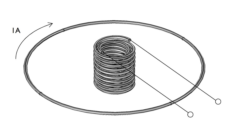
An arrangement of a primary single-turn coil and a secondary twenty-turn coil.
For the multi-turn coil example, the primary coil is modeled with the Single-Turn Coil feature, which is used to excite the coil. The secondary coil is modeled with the Multi-Turn Coil feature. A homogenized approach is used to model the turns of the secondary coil.
The magnetic flux lines are plotted for open and closed circuit cases. The voltage across the secondary coil is computed — an amount that can be used to find the mutual inductance.
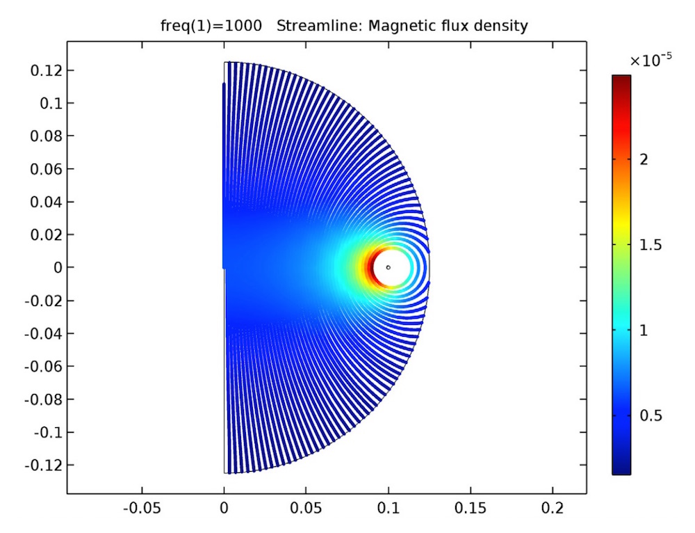
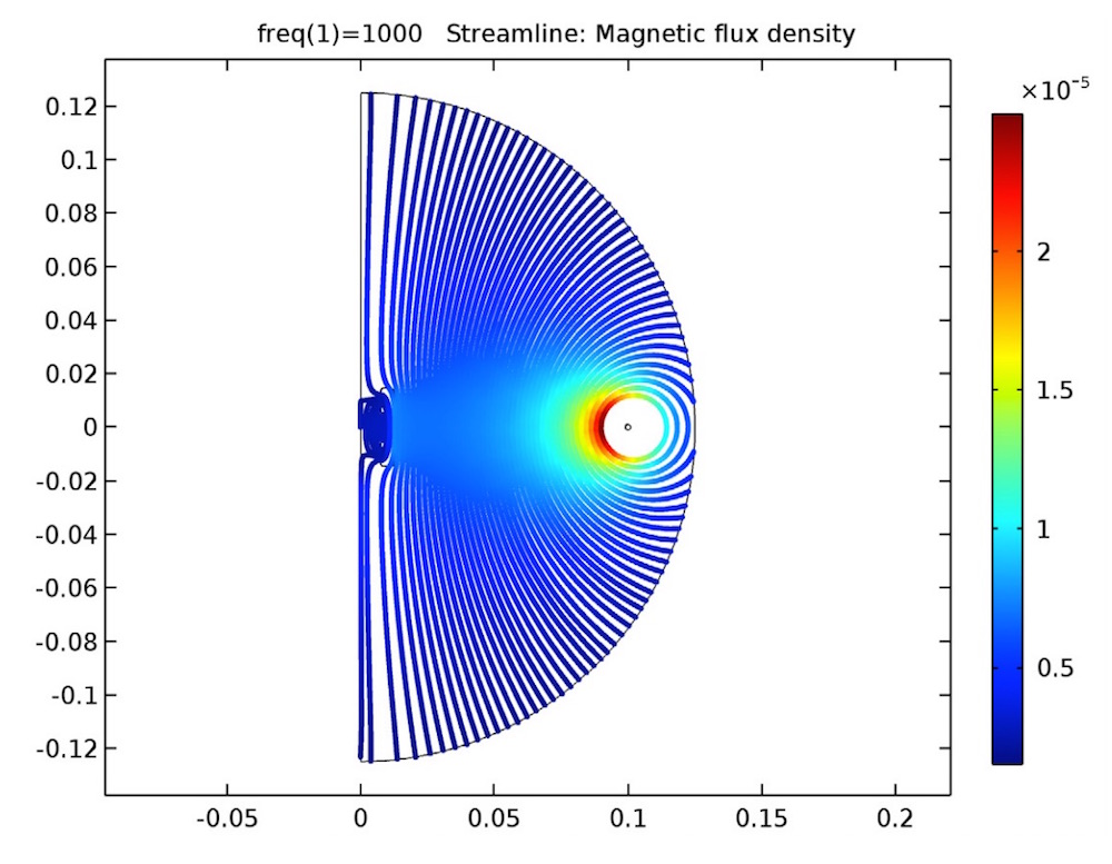
The magnetic flux for a multi-turn coil arrangement in an open circuit (left) and a closed circuit (right).
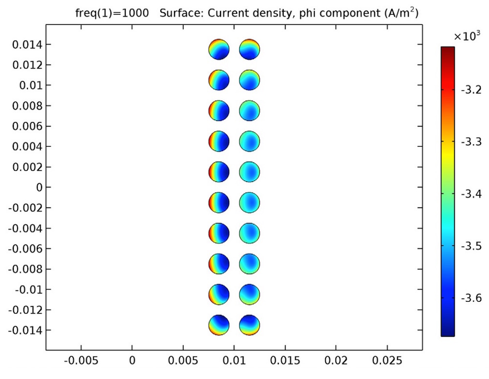
The same arrangement can also be modeled so that each turn of the coil is modeled explicitly. For the coil group example, the primary coil is modeled with the Single-Turn Coil feature. The secondary coil is also modeled with the Single-Turn Coil feature along with an additional Coil group setting. This setting enforces that the same amount of current flows through each turn in the coil and computes the total coil voltage to find the mutual inductance.
The voltage found through the Coil group setting is used to evaluate the mutual inductance, which agrees well with the analytic data.
The magnetic flux lines (left) and induced currents (right) for a coil group arrangement.
COMSOL Multiphysics offers an easy way for computing mutual inductance in a variety of different circuit arrangements. Imagine the possibilities of this functionality within your own simulations.




Comments (0)