
Lithium-ion (Li-ion) batteries are widely known for their energy efficiency and are becoming the battery of choice for designers of electric vehicles (EVs). However, these batteries lose efficiency quickly with sudden changes in temperature. One way to control rises in temperature (whether environmental or generated by the battery itself) is with liquid cooling, an effective thermal management strategy that extends battery pack service life. To study liquid cooling in a battery and optimize thermal management, engineers can use multiphysics simulation.
Thermal Management of a Li-Ion Battery in an Electric Car
Li-ion batteries have many uses thanks to their high energy density, long life cycle, and low rate of self-discharge. That’s why they’re increasingly important in electronics applications ranging from portable devices to grid energy storage — and they’re becoming the go-to battery for EVs and hybrid electric vehicles (HEVs) because of their high energy density compared to their weight.
Despite their many advantages, Li-ion batteries are especially sensitive to extreme low and high temperatures. When a Li-ion battery pack gets too hot or cold due to environmental factors or by its own charge or discharge rate, its performance and life cycle can decrease significantly. Not only that, but once the battery pack is heated or cooled outside its optimal temperature range of 20 to 40°C, even a one-degree change in temperature can make a difference in the safety, charge acceptance, and reliability of the battery management system and the car itself.
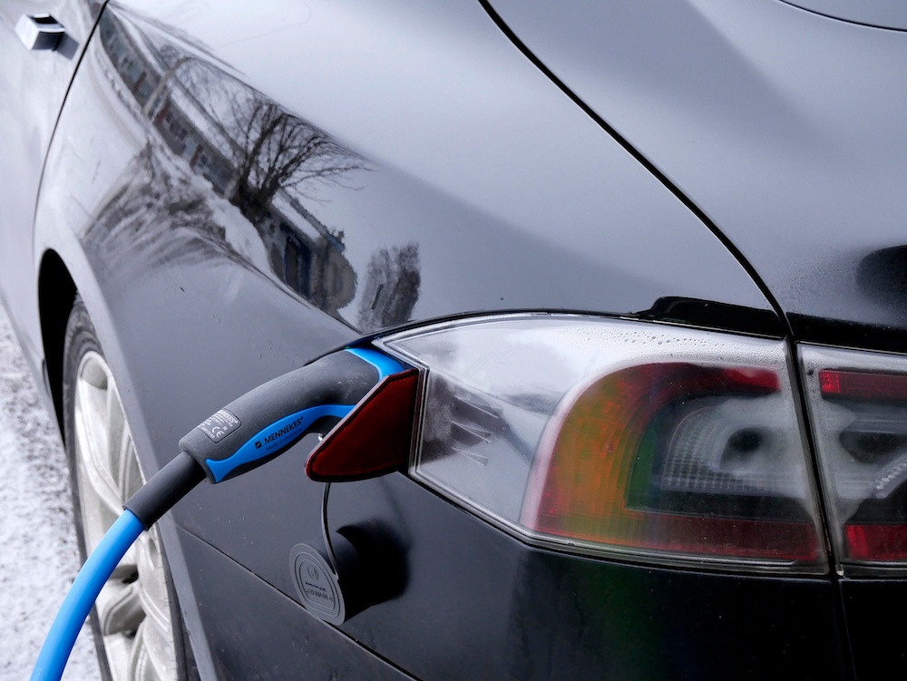
An electric vehicle at a charging station. Image by Santeri Viinamäki — Own work. Licensed under CC BY-SA 4.0, via Wikimedia Commons.
Thermal management helps put the designer back in the driver’s seat by addressing these issues head-on. There are two main temperature-related factors to focus on for long life and optimal battery performance:
- Optimal temperature range of the battery pack
- Uniform temperature distribution within the battery pack and cells
Designers of EVs must also account for other factors when including a battery thermal management system in their designs. Take the size of the thermal management system, for instance: In the overall EV design, safety circuits and hazardous gas removal systems take up space, and the battery packs in EVs have to be large enough to power an entire vehicle. Therefore, the thermal management system can’t be so large or heavy that it interferes with the electric powertrain system performance — but it still needs to be effective enough to quickly remove the amount of heat a larger battery pack generates.
What Are the Most Effective Cooling Systems for Batteries?
A battery in an EV is typically cooled in the following ways:
- Air cooled
- Liquid cooled
- Phase change material (PCM) cooled
While there are pros and cons to each cooling method, studies show that due to the size, weight, and power requirements of EVs, liquid cooling is a viable option for Li-ion batteries in EVs. Direct liquid cooling requires the battery cells to be submerged in the fluid, so it’s important that the cooling liquid has low (or no) conductivity. Indirect liquid cooling does not require the battery cells to be in contact with the liquid. Instead, the liquid coolant can be circulated through metal pipes within the system, which requires the metal to have some sort of anticorrosion protection.
Using COMSOL Multiphysics® and add-on Battery Design Module and Heat Transfer Module, engineers can model a liquid-cooled Li-ion battery pack to study and optimize the cooling process.
Modeling Liquid Cooling of a Li-Ion Battery Pack with COMSOL Multiphysics®
For this liquid-cooled battery pack example, a temperature profile in cells and cooling fins within the Li-ion pack is simulated. (While cooling fins can add more weight to the system, they help a lot with heat transfer due to their high thermal conductivity.)
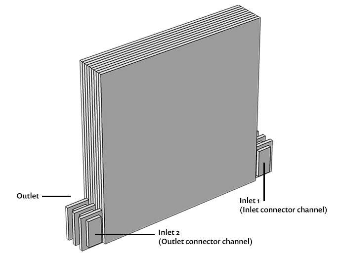
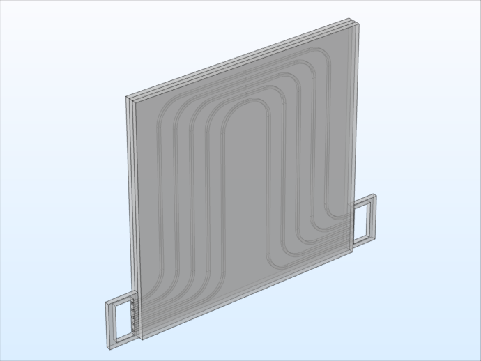
The battery pack geometry, shown below, consists of three stacked repetitive unit cells and two flow connector channels (one on the inlet and one on the outlet side of the cooling fins). Each unit cell within the pack has a cooling fin (2 mm each) with flow channels, with one battery (2 mm each) on each side, resulting in a total thickness of 6 mm.
Left: Battery pack geometry consisting of three unit cells. Right: Unit cell of the battery pack with two batteries and a cooling fin plate with five cooling channels.
The model is set up to solve in 3D for an operational point during a load cycle. For calculating the average heat source and modeling the cells, you can use the same 1D electrochemical model as the one used in the Thermal Modeling of a Cylindrical Lithium-Ion Battery in 3D tutorial model. The battery temperature is set to the inlet temperature of the cooling fluid, and the discharge load is set to a 7.5 C rate.
Assuming that the temperature variations in the battery pack are small, you can use an average temperature for the pack to calculate both the cooling fluid and battery material properties. Likewise, if the variations in heat generation during the load cycle are much smaller than the heat transport within the pack, you can set up the model with the assumption that the thermal balance is quasistationary for the given battery heat source and operational point during the load cycle.
Since we want to solve for the velocity and pressure in the cooling channels as well as solve for the temperature field, we use both the Laminar Flow and Heat Transfer interfaces for this model.
For the flow, the cooling fluid is assumed to have the material properties of water, and the fluid properties are calculated using the inlet temperature as input. The liquid that flows through the cooling plate enters at Inlet 1, while the flows that have passed the cooling fins earlier on in the battery pack enter at Inlet 2. Atmospheric pressure is applied at the outlet.
The heat transfer is set up so that it will solve for the temperature field for the flow compartment, aluminum cooling fins, and batteries. Going back to the model of the cylindrical Li-ion battery in 3D, you can apply the same density, heat capacity, and heat source in the battery domains. Then, for this example, the temperature for the cooling fluid is 310 K for Inlet 1, and a boundary heat flux is applied to Inlet 2. Similarly, an outflow condition is applied at the outlet and further heat flux conditions are applied on other boundaries to account for some heat loss in cases of poor insulation.
Evaluating the Simulation Results for 3 Studies
Once the model is set up with all of the physics in mind, you can solve it in three studies for each physics interface in the following order:
- Fluid flow
- Heat source
- Quasistationary temperature
Let’s take a look at the study results.
For the fluid flow study, you can use a constant inlet temperature so that there is a constant uniform temperature and cooling fluid properties in the channels. In the plot below, you can see the pressure losses in the channels, which could be used to optimize the battery’s flow pump.
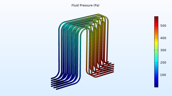
Pressure in the flow compartment.
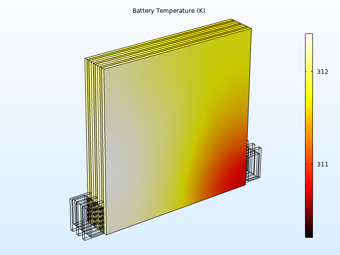
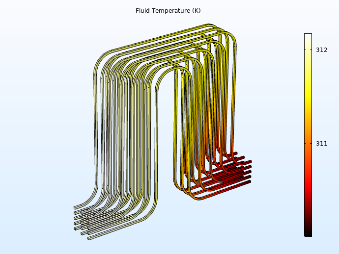
The second study calculates the average heat source for the batteries with a time-dependent study step that solves the electrochemical problem. This study, which is run to a desired time of 60 s, assumes that the temperature in the 1D battery model is constant and equal to the inlet temperature of the cooling liquid. Below on the left is the battery temperature, with a difference of about 3 K between the highest and lowest temperatures. Here, we can see that the temperature variation within the different batteries is smaller than the temperature variation within a single battery. Below on the right, the results for the temperature of the cooling liquid are as expected, showing that the temperatures are slightly lower than in the battery and consistent with the temperature distributions throughout the battery pack.
Further, for the temperature of the second battery in the results below, it appears that the cooling fin is doing its job here — the surface facing the cooling fin is cooler and is at its coolest temperature at the corner of the inlet.
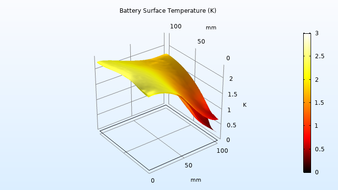
Temperature increase of the second battery at the surface facing the cooling fin and the surface facing the third battery.
Finally, the quasistationary study step uses the flow velocity from the first study and the average heat source from the second study to get the following result: By evaluating the velocity magnitude in a cut plate through the middle of a cooling fin (shown below), we can see that the flow distribution is uniform in the different channels. Since the total flow is high, yielding a small residence time, the battery pack reaches a quasistationary temperature profile quickly after a load change.

Velocity magnitude in the cooling fin, showing that the flow is evenly distributed between the five channels.
By performing time-dependent and temperature analyses of the liquid cooling process in a Li-ion battery pack, it is possible to improve thermal management and optimize battery pack design.
Next Steps
Try modeling a liquid-cooled Li-ion battery pack yourself by clicking the button below. Doing so will take you to the Application Gallery, where you can download the PDF documentation and the model MPH file.




Comments (0)