
Lithium-ion (Li-ion) batteries are used to power a variety of devices, from toys and drones to cellphones and laptops to medical equipment and electric cars. To efficiently power such devices, the temperature distribution inside operating Li-ion batteries needs to be controlled, as deviation from optimal operating temperatures can cause a loss, or failure, in their performance. One way to analyze the temperature distribution in Li-ion batteries is with multiphysics simulation.
In this blog post, we explore how to model the thermal distribution in a Li-ion battery pack and discuss a simulation app that is based on the model.
Simulating Thermal Distribution in Batteries
Thermal modeling of batteries is commonly done using two approaches:
- High-fidelity modeling
- Lumped modeling
High-fidelity modeling provides detailed understanding of battery performance and behavior. High-fidelity modeling can provide insight into, e.g., current and potential distributions within a battery cell, the concentration and transport of lithium ions inside the battery, capacity fade due to battery degradation, and failure mechanisms. While detailed models allow for a deep understanding of an individual battery cell, they are too computationally expensive to be used for predicting the performance of large packs of cells. In addition, for a car manufacturer, who might buy battery cells from a cell manufacturer, it can be difficult to either measure or obtain access to the cell-level model input parameters needed to build a high-fidelity model.
For modeling full battery packs, lumped models can provide acceptable accuracy, at a lower computational cost and with fewer input parameters. Lumped models require input parameters such as:
- Battery capacity
- Initial state of charge (SOC)
- Open-circuit voltage (OCV) versus SOC
- Parameters characterizing voltage or capacity losses
These parameters are readily accessible for designers and manufacturers of battery packs. We’ve previously discussed how parameter estimation can be used to obtain these parameters.
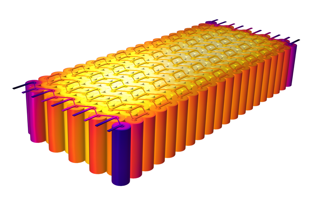
An illustration of a battery module consisting of 200 cells, as rendered in the Lithium Battery Pack Designer app, which is further discussed towards the end of this blog post.
In the following section, we share an example of a thermal model of a battery pack constructed using the lumped modeling approach. The pack geometry is set up in 3D and the Lumped Battery interface is used to define the thermal properties for the individual cells.
Note: If you’d like to jump right into the step-by-step of building this model, feel free to download it here: “Thermal Distribution in a Pack of Cylindrical Batteries”.
The Lumped Modeling Approach in COMSOL Multiphysics®
Let’s look at how to model the temperature distribution in a battery pack during a 4C discharge.
The battery pack (or module) we’ll model consists of 6 pairs of cylindrical batteries connected to create a 6 cell in series, 2 in parallel (6s2p) configuration, which is common in portable devices such as toys and medical equipment. Note that the same procedure may be used to model several hundreds of cell, for example in a battery module in a car, see the battery module figure above.
The use of two planes of symmetry ensures that temperature distribution only needs to be computed for three individual battery cells. Three instances of the Lumped Battery interface are added to define the respective heat sources, which are then coupled to one Heat Transfer interface.
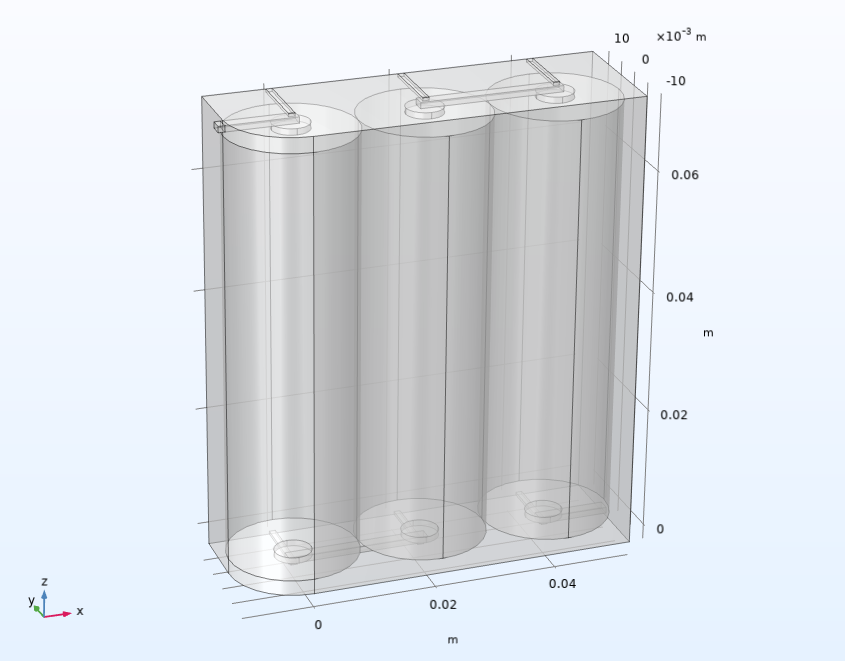
The model geometry.
The position of the batteries in a pack influences their operating temperature. In the model, three 21700 battery cylinders (21 mm in diameter, 70 mm high) are placed adjacently to each other. Small connecting strips of aluminum are located at the top and bottom of the cylinders, according to the 6s2p configuration. The whole pack is assumed to be wrapped in plastic, forming a domain filled with air. Assuming a nominal capacity of 4 Ah for each cell and nominal voltage of 3.7 V, the battery pack has a total nominal capacity of approximately 178 Wh.
Each Lumped Battery interface used to model an individual battery cylinder has temperature-dependent ohmic, exchange-current, and diffusion time-constant parameters. The temperature profile is modeled using a Heat Transfer interface, where the heat sources stemming from the battery models are added using an Electrochemical Heating multiphysics node; therefore, each cell has an individual lumped model.
In this model, we have chosen to neglect the convection in the air-filled domain enclosing the batteries, assuming quiescent conditions. The outer boundaries of the battery pack are cooled with a convective cooling condition. For the interior flat symmetry boundaries facing the rest of the pack, symmetry (no-flux) conditions are used.
The thermal conductivity in each battery cell is anisotropic, defined via cylindrical coordinate systems for each battery cylinder following the structure of the jelly roll inside the battery, which consists of the metal foils, electrodes, and separator inside the cell. The jelly roll has a lower thermal conductivity in the radial direction compared to the angular and z directions — a result of the spirally wound metal foils in the jelly roll.
The pack is discharged from 100% to 20% SOC using a 4C rate for 12 minutes. Probes for temperature and cell potential are added to different cells to allow for a visual representation of the results while solving.
Surface temperature in the battery pack after 12 minutes.
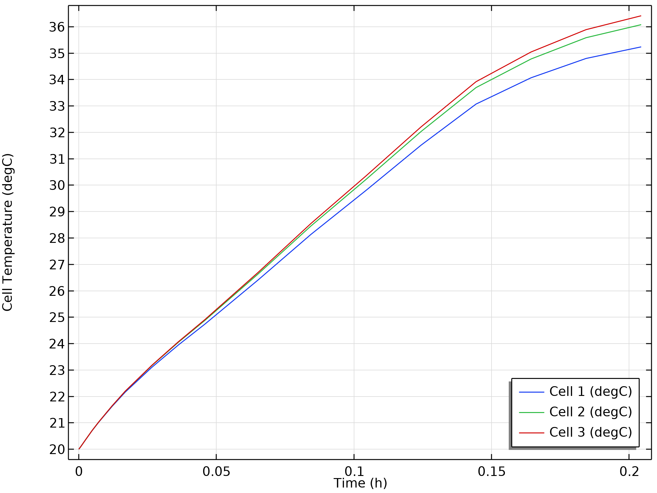
We can observe that the innermost parts of the pack experience a temperature about 2ºC higher than the outermost parts, which can grow to tens of degrees in a larger battery module.
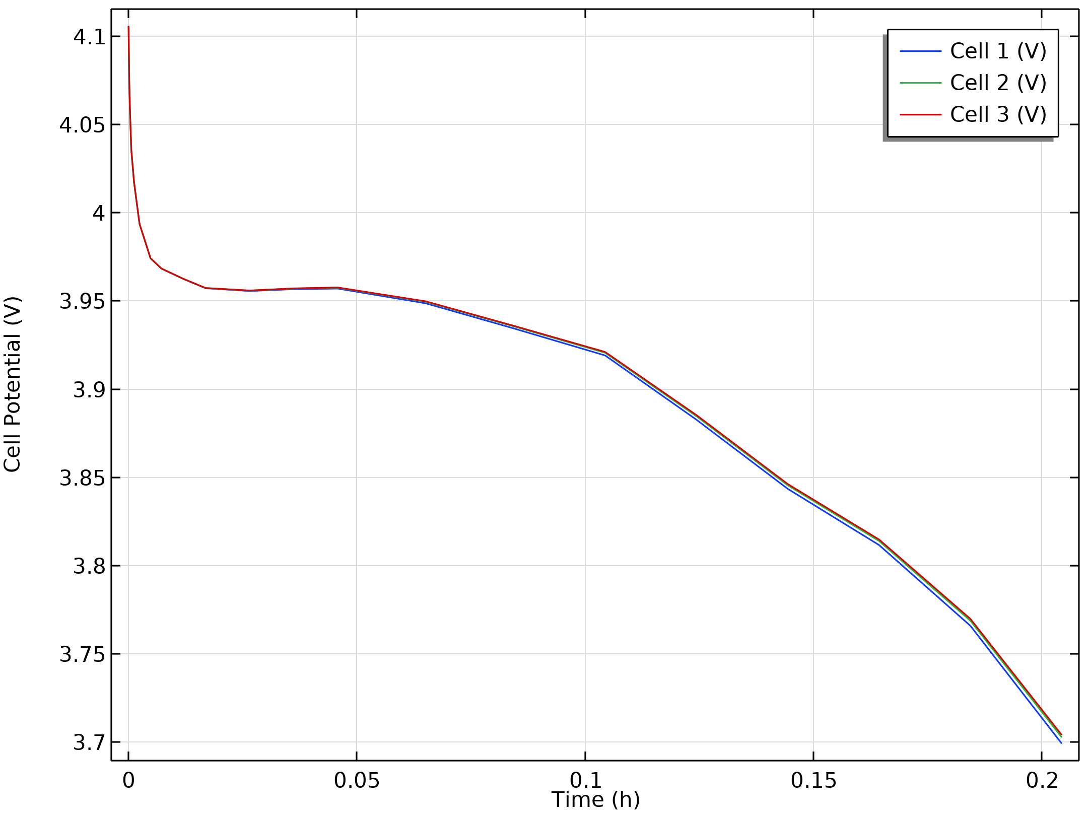
As you can see in left-hand plot below, the outermost cell (Cell 1) exhibits a slightly lower discharge voltage, which is a result of the ohmic losses and exchange current being slightly lower, and the diffusion time constant being slightly higher, for the lower temperature. The corresponding temperatures are shown in the figure on the right below.
Individual cell voltages during discharge (left) and average cell temperatures over time (right).
Modeling a Battery Pack with 200 Cells
As discussed, the abovementioned battery pack model is a 6s2p configuration; however, the Lithium Battery Pack Designer app, discussed in the following section, can be used to model a battery pack with several hundreds of cells. With the app, it still takes less than a minute to solve the problem for a given operating current!
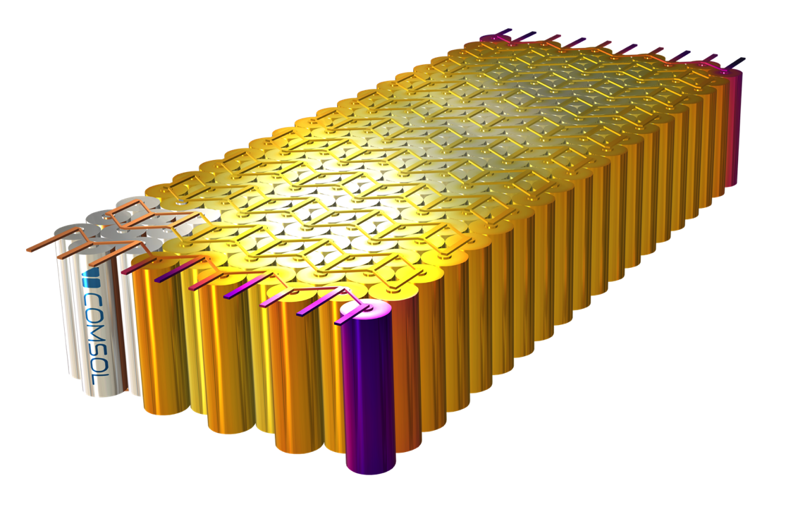
A model of a battery pack consisting of 200 cells, constructed with the app.
Using Simulation Apps to Optimize the Battery Design Process
The powerful computational capabilities of the COMSOL® software can also be utilized by users who are not simulation experts. The Application Builder in COMSOL Multiphysics allows simulation experts to create user-friendly apps that leave out the details associated with building the model and focus only on the parameters the user wishes to control.
One example of a user-friendly simulation app is the Lithium Battery Pack Designer app, available in the Application Library. Using experimental data, the user can first estimate battery cell parameters such as the ohmic overpotential, diffusion time constant, and dimensionless exchange current. Then, the user can select pack design parameters (packing type, number of batteries, configuration, and geometry), battery material properties, and operating conditions. Finally, using the parameterized battery cell model in the chosen pack design, the user can simulate the dynamic voltage and thermal behavior of the battery pack as a whole.
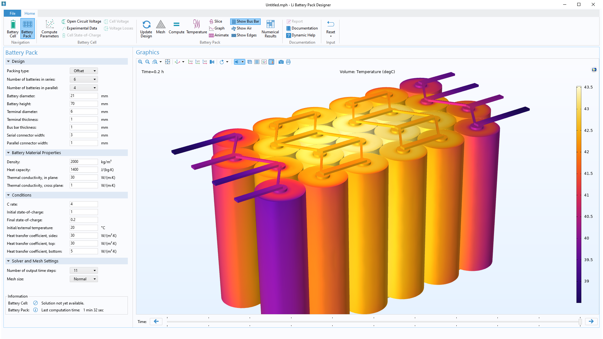
The Lithium Battery Pack Designer app.
Next Steps
Download the model file and simulation app to try modeling a Li-ion battery’s thermal performance:
- Tutorial model: Thermal Distribution in a Pack of Cylindrical Batteries
- Demo app: Lithium Battery Pack Designer
Further Reading
Want to learn more about Lithium-ion battery modeling? Check out these related resources:




Comments (3)
Heri Rustamaji
May 20, 2022Thank you, Neena Picardo. It is a great article for simulation. At another time hope you will share about supercapacitor thermal modeling.
Salih Kaya
February 18, 2023After defining materials to domains in COMSOL, why does it want materials to boundaries as well?
Nilanjan Mondal
August 9, 2023Thank you Neena for this knowledgable article.