
While aligning bearings can help extend the lifetime of rotating machinery, doing so can be expensive. To determine the amount of alignment that delivers the best performance at the lowest cost, engineers can investigate the effect of bearing misalignment in a rotor system using simulation, accounting for factors like the intended operating speed and power ratings. In this blog post, we will look at a rotor system with misaligned bearings and analyze its response to study the effect of the misalignment.
The Importance of Analyzing Bearing Misalignment
Aligning the bearings in rotating machinery during assembly is a principal requirement for reasons such as:
- Longer plant life and higher reliability
- Reduced noise emission and vibration levels
- Reduced cost of bearing replacement
- Reduced maintenance
- Higher operational availability of the equipment
However, alignment comes with its own cost in terms of the manpower needed and larger downtime of the equipment. How much effort should be put into aligning bearings, particularly when there are many of them? In other words: How precise should the alignment be? For different industrial equipment, the answer may vary depending on the operating angular speed, power ratings, expectations of the user, etc.
Usually, alignment is done when the equipment is not really operational. In actual operating conditions, the shaft may bend due to factors such as external loads, self-weight, imbalances in the rotor, and temperature gradients. This bending again leaves the bearings misaligned in actual operating conditions. Although some corrections for this can be done a priori, it is not possible to get rid of the misalignment completely. Simulations can help in assessing the effects of the misalignment and its permissible range to ensure the safe operation of the equipment.
Let’s take a look at how to analyze bearing misalignment using the COMSOL Multiphysics® software.
Analyzing Vibrations in a Gear Drive with Bearing Misalignment in COMSOL Multiphysics®
Consider a very simplified model of a gearbox with only a single gear pair, as shown in the figure below. Both the driving and driven shafts are supported at both ends by deep groove ball bearings.
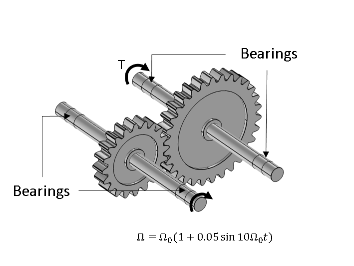
The shaft with the smaller gear is the driving shaft and the shaft with the larger gear is the driven shaft. The driving end of the driving shaft is prescribed an angular velocity of \Omega = \Omega_0(1+0.05\sin 10\Omega_0 t), with \Omega_0 = 16.67 rad/s. The output of the driven shaft has the loading torque T = 100 Nm, which becomes active only after the driving shaft completes 1/8 of a revolution. Other parameters for the gear drive are given in the table below.
| Shaft | |
|---|---|
| Length | 300 mm |
| Diameter | 20 mm |
| Gear 1 | |
| Number of teeth | 20 |
| Pitch diameter | 100 mm |
| Pressure angle | 25° |
| Gear 2 | |
| Number of teeth | 30 |
| Pitch diameter | 150 mm |
| Pressure angle | 25° |
| Backlash |
1 mm |
| Bearings | Type | Deep groove ball bearing |
| Number of balls | 20 |
| Ball diameter | 1.33 mm |
| Pitch diameter | 21.33 mm |
| Inner race contour radius | 2 mm |
| Outer race contour radius | 2 mm |
The Multibody Dynamics interface allows you to model the gear drive assembly. A model of a deep groove ball bearing is available as the Radial Roller Bearing node in the Multibody Dynamics interface, but it requires the Rotordynamics Module, an add-on to COMSOL Multiphysics. The rotation of the driving shaft is specified using the Prescribed Motion subnode on the Hinge Joint, and the loading torque on the driven shaft is applied using the Applied Moments subnode on the Rigid Connector. The Joint Elasticity subnode on the Hinge Joint is used to free all other degrees of freedom.
The physics nodes for modeling the gear drive are shown in the figure below.
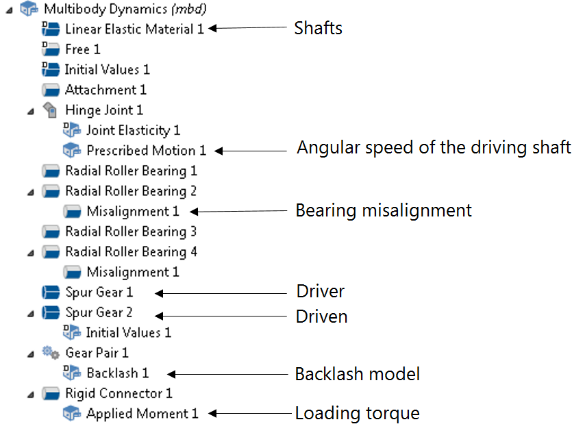
A time-dependent simulation with the time step T0/2000 is performed for a total duration T0 to obtain the response of the gear drive assembly. The term T0 is the time required for one revolution of the driving shaft.
How Bearing Alignment Affects the Vibration
To understand the impact of misalignment on the response of the system, let us consider the following cases:
- All the bearings are aligned perfectly with the shaft
- Two of the bearings are misaligned with the shaft axis, as shown in the figure below
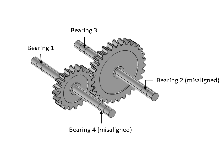
Bearing 2 has an angular misalignment of 0.1° about the local z-axis and Bearing 4 has an angular misalignment of 0.2° about the local y-axis.
The angular speeds of the shafts for the two cases are shown in the figure below.
Angular velocity of the gears with perfectly aligned bearings (left) and with misaligned bearings (right).
Before the driven shaft is loaded (t < 0.047 s), the inertia of the gear drive assembly causes the gears to rattle in the presence of backlash. The rattling of the gears induces torsional vibration in the shafts. Therefore, the wheel (driving gear) follows the prescribed speed of the driving shaft in an average sense with a certain amount of fluctuations. The pinion (driven gear), due to backlash, does not respect the gear ratio during idling. The driven shaft is loaded after t = 0.047 s. This induces even more torsional vibration in the shafts, and large deviations in the angular speed from the prescribed value are seen. At a later time, when the fluctuations have been reduced, the wheel follows the prescribed speed. In the presence of misalignment, torsional vibrations in the shaft continue due to the periodic misalignment forces in the bearings.
To understand the rattle in the gear, you can plot the gear mesh contact force, shown below. When the driven shaft is not loaded, the contact force is intermittent, clearly demonstrating the rattling behavior. Once the shaft is loaded, the contact force becomes continuous, indicating the absence of rattling. When loaded, the contact force keeps fluctuating due to the varying angular speed and the torsional vibrations in the shafts.
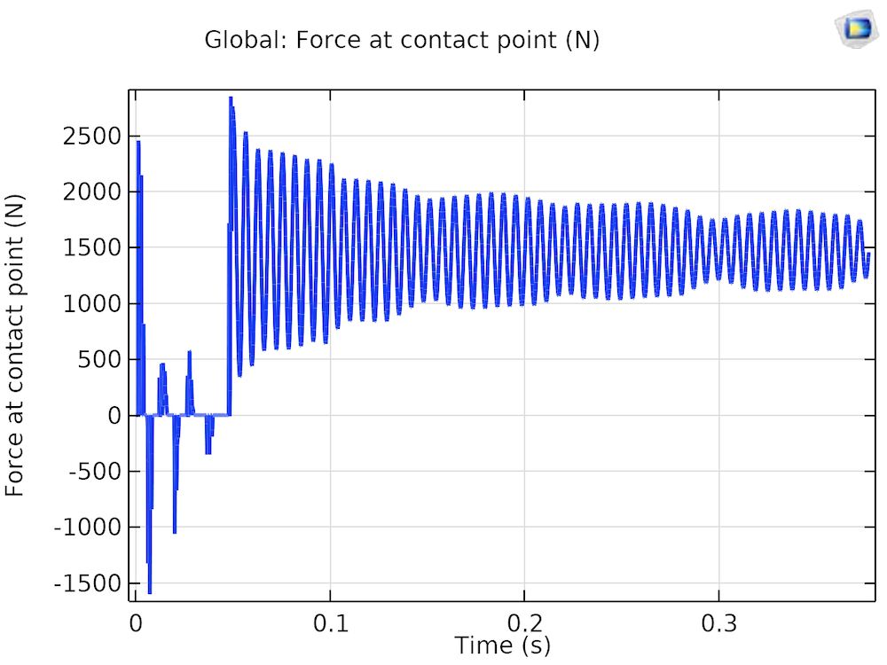
Gear mesh contact force.
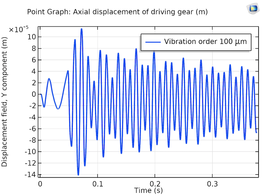
One of the most important characteristics of a rotary system with misalignment is the presence of axial vibrations in the response. The axial vibration in the shaft at the gear location is compared in the figures below for the two cases.
Axial displacement of the driving gear with perfectly aligned bearings (left) and misaligned bearings (right).
As expected, for the perfectly aligned bearings, axial vibrations of the driving gear are negligible, whereas this vibration becomes significant in the presence of misalignment. Therefore, axial vibration measurement can be used as one of the parameters for identifying bearing misalignment. The frequency spectrum of the axial displacement for the driving gear in the presence of bearing misalignment, illustrated in the figure below, clearly shows that the synchronous response is dominant in the spectrum.
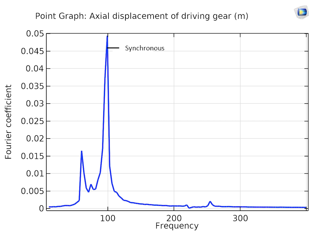
Frequency spectrum of the axial displacement of the driving gear for misaligned bearings.
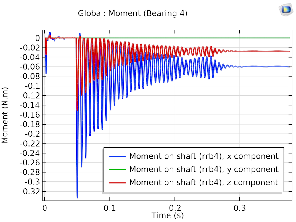
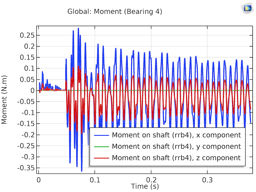
The bearing reaction moment on the shaft is very sensitive to misalignment in the bearing. Plots of the bearing moment for aligned and misaligned bearings are shown below.
Moment on the shaft for an aligned (left) and misaligned (right) bearing.
For the aligned bearing, just after the driven shaft gets loaded, its moment fluctuates due to the bending vibrations in the shaft. There is a reduction in the amplitude, and eventually, the bearing moment follows the bending vibrations due to the fluctuation of the driving speed. For the misaligned case, the bending vibrations induced during the loading of the driven shaft have a longer duration. Reaction moments in both the aligned and misaligned cases are approximately in the direction opposing the bending of the shaft due to the gear mesh force. However, in the misaligned case, the reaction moment keeps fluctuating with a high amplitude, keeping the bearing dynamically loaded throughout the operation.
During the mounting, bearings can be kept intentionally misaligned by an amount equal to the tilting of the shafts due to gear mesh forces, as to keep them aligned during their operation. This will help to reduce the moment reactions in the bearings and increase their life.
From the response of the system above, it is clear that misalignment creates sustained vibrations in the system, resulting in fatigue of the components and thus reducing their life. Also, these vibrations can result in wear of the inner and outer races of the bearing due to dynamic loading, thereby causing bearing failure long before its normal operational life. Simulation can help in assessing the vibration level in rotating systems and thus predicting the life of these components. Design changes can be evaluated using the simulations to come up with the optimum design before prototyping, reducing the overall cost of design and testing.
Further Reading
Find out more about bearing simulation in the following blog posts:




Comments (3)
Trevor Munroe
July 11, 2019Hello Prashant,
Nice blog. I am trying to duplicate your model. Some questions. Relative to the rotor and/or ball, how is the local bearing axis defined (Bearing axis, local y direction)? I look for an illustration in the Multibody documentation but I did not see such a image. Also, ball bearing thrust model is also possible in COMSOL?
Trevor
Prashant
July 12, 2019 COMSOL EmployeeHi Trevor,
Thanks for your comments. Bearing axis is defined with respect to the global directions also should be along the shaft axis. In this particular model global y direction was representing the bearing axis. Bearing local y-direction is not very important in terms of modeling the bearing but is simply needed for the postprocessing. For example to the know the bearing reactions in corresponding local directions. Local y axis is direction along which the first rolling element is kept rest of the rolling elements are positioned relative to this depending on the total number of rolling elements. So azimuthal coordinates of the rollers are referred with respect to local y direction with first roller being at the azimuthal angle zero.
Currently we do not have the functionality to model the thrust roller bearings.
Trevor Munroe
July 12, 2019Thanks for the reply, Prashant. I look forward to a thrust roller bearing functionality.