
Wastewater often contains organic and inorganic materials, which can be nonbiodegradable and even toxic. To reuse wastewater, these contaminants are removed via physical, chemical, and biological processes. Clarifiers treat wastewater by separating the particles via sedimentation, but their performance is affected by factors such as settling, turbulence, the ratio of the particles’ outer surfaces to mass, sudden direction changes in the flow, and the velocity profile. To design clarifiers for effective wastewater treatment, engineers can turn to fluid flow simulation.
Ensuring Sustainable Water, from Congressional Laws to Treatment Plants
As concerns over climate change rise, the conservation and reuse of water is a pertinent discussion. For instance, the EPA issued best practices for water management and countries are passing laws that make it safer to reuse water. The U.S. Congress passed the Microbead-Free Waters Act in 2015 (with Canada, New Zealand, and the United Kingdom soon following suit) to prohibit the manufacture and distribution of rinse-off cosmetics containing microbeads. Plastic microbeads, which are often found in exfoliating shower gels, are nonbiodegradable and get rinsed down the drains and into our wastewater.
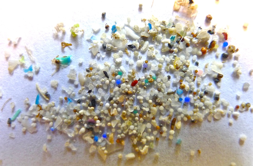
Microbeads and other microplastics commonly found in bath products prior to the 2015 ban in the U.S. Image by Oregon State University. Licensed under CC BY-SA 2.0, via Flickr Creative Commons.
Even with steps toward banning harmful contaminants, treatment plants still rely on physical, chemical, and biological processes to clean wastewater. Engineers working with wastewater treatment and contaminant removal processes can use simulation to study and design clarifiers.
How Does the Wastewater Treatment Process Work?
Wastewater treatment involves two main stages:
- Physical methods, such as using clarifiers to separate solids and oils from water
- Bacterial degradation of pollutants, such as chemical oxidation, an advanced aeration technique
Clarifiers, one primary treatment method, rely on sedimentation, the process by which gravity is used to remove suspended solids from water. In the physical wastewater treatment process, solid particles are removed through sedimentation, aided by flocculation and filtration. Flocculation is obtained by adding coagulants, which leads to aggregation of very small particles to form flocs. Again, sedimentation removes these flocs.
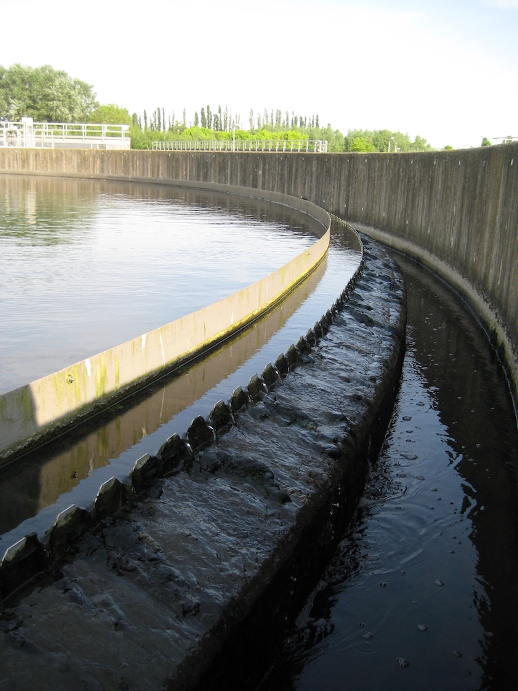
Close-up view of a secondary circular clarifier. Image by Annabel. Licensed under CC BY-SA 3.0, via Wikimedia Commons.
During sedimentation, gravity causes flocs to fall toward the bottom of a clarifier tank. But there are many other processes at work that should be considered in the clarifier design.
The influent well is placed in the middle of the clarifier with the inlet at the bottom of the well. After ejection at the inlet, the larger heavy particles fall close to the middle of the clarifier almost immediately. This is due to their large mass-to-outer-surface ratio. The smaller heavy particles (those that are not small enough to form flocs) follow the main flow until there is a sharp change in direction of the flow. For example, if the main water flow in the clarifier changes from a downward to upward direction, then the heavier particles continue to fall and gather at the bottom of the clarifier, where they slowly leave through the sludge outlet. The clarified water exits at the peripheral outlet.
Turbulence can impede the formation of flocs and also break up flocs that are formed as they fall to the bottom of the tank, causing the very small particles to follow the water flow through the peripheral outlet. Turbulence can also transport small particles from the center to the periphery of the tank so rapidly that they never have time to settle (or to form flocs and then settle). The risk of mixing explains why the peripheral outlet of a typical clarifier is very large. The flow velocity decreases substantially with the radius, which causes less turbulence, less turbulent mixing, and larger residence time for each stream that travels through the clarifier outlet (giving enough time for particles to settle).
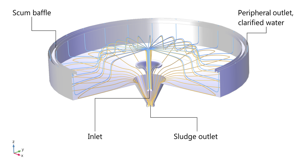
A 3D view of a secondary clarifier model. The blue streamlines show a possible path for the clarified water, while the dark-yellow streamlines show a path for the dispersed solid phase, consisting of very small but heavy particles. The solid phase follows the flow of water until it takes a steep turn upward, where the higher density forces the heavy particles to take a lower path down to the sludge outlet.
By modeling a circular secondary clarifier using the CFD Module, an add-on to the COMSOL Multiphysics® software, we can study how different factors affect the contaminant removal process for wastewater.
Modeling the Flow in a Secondary Clarifier with COMSOL Multiphysics®
The model geometry for the secondary clarifier has a diameter of 24 m and a varying depth between 3.3 m and 4 m. Due to axial symmetry, we can simplify the model geometry from 3D to 2D axisymmetry (see the figure below). The inlet is at the bottom of the influent well at the center of the tank, as shown below. Here, the mixture of solids and water enters the clarifier in the form of a jet. There are two outlets: the sludge outlet at the bottom and the peripheral outlet where the clarified water leaves the clarifier. The flow rate is slow enough to assume a flat horizontal water surface.
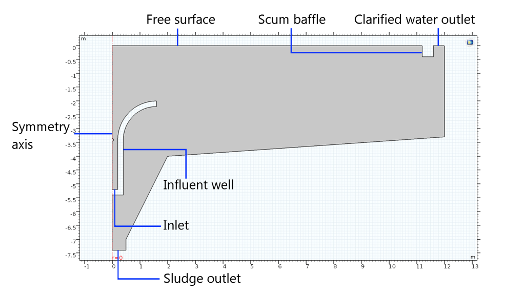
Geometry of the circular clarifier in 2D.
The particles, including the flocs, are assumed spherical and of equal size and form the so-called dispersed phase. The k-ε turbulence model is used in combination with the mixture model for two-phase flow including gravity as volume force. The initial conditions are zero velocity, zero relative pressure, and zero solid phase volume fraction in the entire clarifier.
The boundary conditions are set as follows:
- Inlet:
- Velocity of 1.25 m/s
- Dispersed phase volume fraction: 0.003
- Turbulence intensity: 5%
- Length scale: 0.07*rin (where rin = 0.2 m is the radius of the inlet)
- Velocity of 0.05 m/s at the sludge outlet
- Zero relative pressure at the peripheral outlet
- Slip conditions at the free surface
- No-slip conditions at the walls
- Axial symmetry at the symmetry axis
Evaluating the Simulation Results
After 12 hours, the flow in the clarifier reaches steady state. We can see below that the dispersed phase volume fraction is higher at the bottom, as expected, but that turbulent mixing tends to spread out the particles, forming a smooth volume fraction profile. Also, we can see that the dispersed phase volume fraction profile is sharper as mixing decreases with distance from the center, since flow rate and hence also turbulence decrease as the mixture flows away from the inlet.
At the peripheral outlet (top right of the plot below), the particles and flocs have been allowed to settle enough to give a clear effluent (clarified water). Note that the maximum volume fraction of the dispersed phase (particles and flocs) is less than 1% in the whole clarifier, which verifies that the mixture model is accurate.
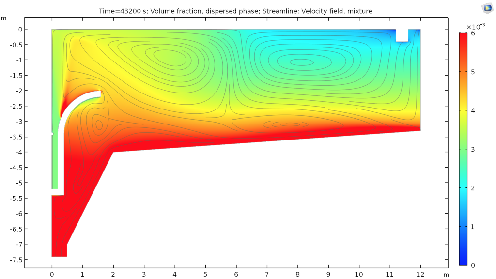
Mixture-velocity streamlines and solid phase volume fraction after 12 hours.
The dispersed phase mass flow rates at the inlet, peripheral outlet, and the sludge outlet are shown below. Using these results, we can calculate the particle removal rate. The calculations show that the clarifier removes 0.52 – 0.10 = 0.42 kg solid particles per second. Thus, the separation efficiency of the secondary clarifier is 81%.
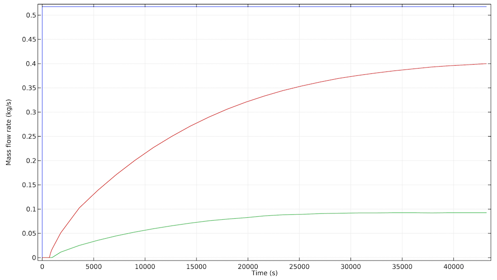
Mass flow rates of the dispersed phase at the inlet (blue), peripheral outlet (green), and central outlet (red).
Finally, we can study the volume fraction of the dispersed phase and streamlines for both dispersed and continuous phases after 12 hours. We can see that the streamlines for the dispersed phase tend to move downward to a higher extent as the flow reaches the outer wall of the clarifier, while the continuous phase (water) tends to move upward toward the peripheral outlet to a higher extent.
There are two large recirculation zones close to the surface. The first one is found close to the center in the wake of the inlet jet. The second one is created by the mixture falling to the bottom at the edges of the first zone and the clarified water moving outward at the peripheral outlet of the clarifier. The dispersed phase tends to follow the lower path of the second recirculation zone and does not follow the streamlines up to the surface in this second zone.
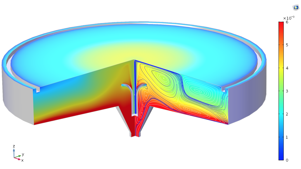
Cut through the swept-out volume of the clarifier with streamlines for the dispersed (blue) and continuous (white) velocity fields.
We can easily modify the secondary clarifier model for more advanced analyses by:
- Adding baffles to the geometry
- Changing the inlet and outlet velocities
- Increasing the dispersed-phase volume fraction in the sludge
- Changing the density and size of the dispersed particles
Next Steps
You can try modeling a secondary clarifier by clicking the button below.
Further Reading
To learn more about simulating mixers, check out these blog posts:


Comments (2)
Moon Stone
December 27, 2019Yangjiang is a professional oil recycling machine manufacturer in China. It has a professional and effective research & development team. We can provide the highest-quality products for customers from all over the world. For more information, please click here. https://www.oilrecyclingplant.com/index.html
cebo ntuli
July 11, 2020This is amazing work sir. Wow