Many modern devices leverage piezoelectricity. When analyzing the design of such devices, you want to be confident in the reliability of the obtained results. By utilizing the COMSOL Multiphysics® simulation software, you can achieve accurate results quickly. To prove it to you, we have created a benchmark model of a piezoelectric transducer.
Piezoelectricity Powers Innovative Technology
Imagine a smart flooring technology that generates power from people’s movements. As their footsteps apply stress to the floor, a certain degree of energy is produced that helps to power lighting and other electrical needs throughout a particular building or environment. At the root of this technology, and many other innovative designs, is piezoelectricity.
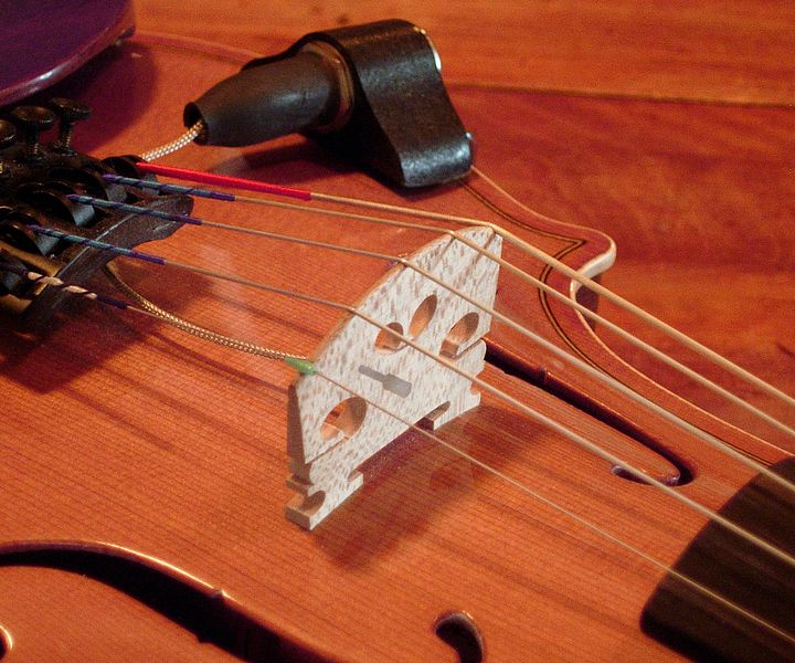
Since the discovery of piezoelectricity in 1880 by the French physicists Jacques and Pierre Curie, this technology has been utilized in a variety of applications, from generating and detecting sounds to producing high voltages. You can even see the piezoelectric effect at work in the use of push-start propane barbecues, time reference sources within quartz watches, and musical instruments.

A piezoelectric violin bridge pickup. Image by Just plain Bill — Own work. Licensed under CC BY-SA 3.0, via Wikimedia Commons.
Optimizing the design of these and other piezoelectric devices requires the use of computational tools that deliver accurate results. COMSOL Multiphysics provides such reliability, giving you greater assurance of the validity of your simulation findings.
To illustrate this, we’ve created a benchmark tutorial of a composite piezoelectric transducer. While the tutorial is a particularly useful resource for those performing ultrasonic transducer simulations, it also serves as a helpful foundation in the simulation of surface and bulk acoustic wave filters.
Analyzing a Composite Piezoelectric Transducer in COMSOL Multiphysics®
The example model of a piezoelectric transducer presented here consists of a 3D cylindrical geometry, which features a piezoceramic layer, two aluminum layers, and two adhesive layers. The layers are organized in such a way that the aluminum layers are at each end, connected to the piezoceramic layer by the two adhesive layers. In an effort to reduce memory requirements, we make use of the model’s symmetry when creating the geometry. This involves making a cut along a midplane that is perpendicular to the central axis and then cutting a 10-degree wedge.
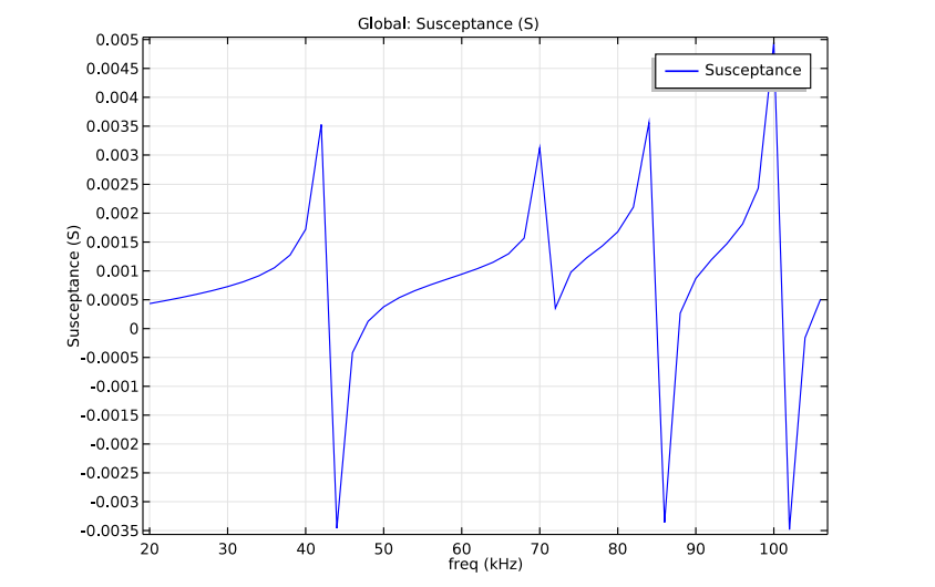
The system operates with an AC potential applied on the electrode surfaces of each side of the piezoceramic layer. For this specific example, the potential has a peak value of 1 V within the frequency range of 20 kHz to 106 kHz. The goal of the simulation study is to calculate the admittance for a frequency range that is close to the structure’s four lowest eigenfrequencies.
We begin our analysis by identifying the eigenmodes and then running a frequency sweep across an interval that includes those first four eigenfrequencies. With its built-in functionality, COMSOL Multiphysics is able to assemble and solve the mechanical and electrical parts of this problem at the same time. This not only fosters greater efficiency in the simulation workflow, but also helps ensure that your results are accurate.
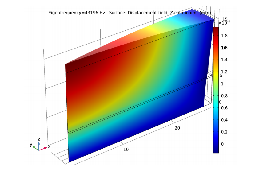
Left: A simulation plot of the lowest vibration mode. Right: A graph comparing susceptance and frequency.
Let’s take a look at the simulation results. The left plot above shows the lowest vibration eigenmode of the piezoelectric transducer, while the plot on the right highlights the input susceptance (the imaginary part of admittance) as a function of excitation frequency. These results agree with the findings presented in the paper “Finite Element Simulation of a Composite Piezoelectric Ultrasonic Transducer” (see Ref 1.). Note that because we did not use damping in this particular simulation, there is a small discrepancy near the eigenfrequencies. However, you can also simulate damping with COMSOL Multiphysics.
Advance the Design of Piezoelectric Devices with COMSOL Multiphysics® and the MEMS Module
Designing reliable piezoelectric devices is possible with tools like COMSOL Multiphysics. Its flexibility and functionality provides you with accurate results that will leave you feeling confident and pave the way for the continued advancement of your piezoelectric devices. To learn more about these capabilities, browse the resources below.
Learn More About Modeling Piezoelectric Devices
- Interested in using COMSOL Multiphysics to model your piezoelectric devices? Contact us today so we can help you evaluate the software
- Download our benchmark tutorial: Composite Piezoelectric Transducer
- Browse further blog posts relating to piezoelectricity:
References
- Y. Kagawa and T. Yamabuchi, “Finite Element Simulation of a Composite Piezoelectric Ultrasonic Transducer”, IEEE Transactions on Sonics and Ultrasonics, vol. SU-26, no. 2, pp. 81-88, 1979.


Comments (0)