
The COMSOL Multiphysics® software is built from the ground up to be multiphysics capable so that the user can easily combine models representing different physics phenomena in whichever way they wish. Sometimes this can be achieved simply by using built-in features of the software, but in other cases, the user will need to do a little bit of extra work. Let’s look at such a workflow in the context of building a magnetohydrodynamic (MHD) model.
Modeling the Multiphysics of Magnetohydrodynamics
The modeling of MHD phenomena is intrinsically a multiphysics problem; one must numerically solve for the coupling between fluid flow, current flow, and magnetic fields. These different fields are all described by partial differential equations, which can be solved for via the finite element method.
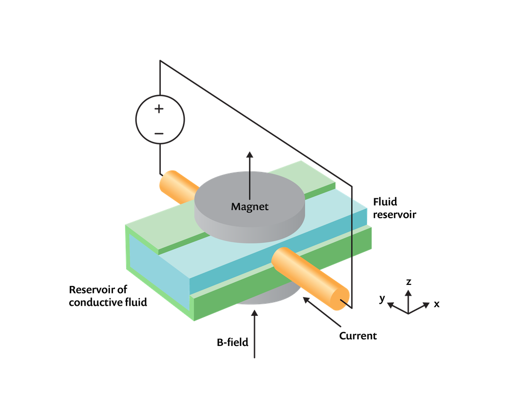
An MHD problem of a conductive fluid in a channel between two magnets with applied current.
Let’s look at how to do this in the context of a relatively simple-looking problem, as sketched above, of an incompressible conductive fluid within an insulative rectangular channel that connects two infinite reservoirs (not modeled) of equal hydrostatic pressure. There are two electrodes protruding through the flow channel on either side that drive an electrical current through the fluid by applying a potential difference. In addition, two circular magnets are placed above and below. The magnets set up a static magnetic field, \mathbf{B}, such that the fluid with conductivity, \sigma, moving with a velocity, \mathbf{v}, through this field will experience induced currents of \mathbf{J} = \sigma \left( \mathbf{v \times B}\right) . In addition to these induced currents, there are currents that arise as a consequence of the boundary conditions on the electric potential field, V, so that the total current in the fluid becomes:
This current, flowing through the magnetic field, will lead to a volume force on the fluid of \mathbf{F = J \times B} , and this will act to pump the fluid from one reservoir to the other. We will assume that the system operates at steady state.
Coupling the Electric, Magnetic, and Flow Fields
For this problem, we need to solve a system of partial differential equations within the fluid to describe the electric and magnetic fields. The equations are the following:
and
This set of equations is solved via the Magnetic and Electric Fields interface, which is part of the AC/DC Module, using the Ampère’s Law and Current Conservation feature along with the separate Velocity (Lorentz Term) feature.
In the space surrounding the moving fluid, there is no current flow, so we only need to solve the single vector equation:
where \mathbf{B_r} is the remanent flux density, which is only nonzero in the magnet domains. When solving solely the above equation, use the Ampère’s Law feature available within the Magnetic and Electric Fields interface.
We assume that the properties of the channel walls do not affect the fields and thus omit them from the model. A set of material properties and boundary conditions are used that will give illustrative results. The magnetic field boundary conditions everywhere are the Magnetic Insulation condition, except for on the xy-plane, where the Perfect Magnetic Conductor condition is used to exploit the symmetry of the system. The domains representing the electrodes must extend all the way to the boundary of the modeling domain, touching the Magnetic Insulation boundaries, to provide a current return path. The Ground and Terminal of type Voltage are applied on these exterior faces, while Electric Insulation conditions are applied on all other applicable boundaries.
In addition, we also need to solve for the flow field in the channel. We will assume that the flow is laminar and thus solve the Navier–Stokes equations in the channel domain. If the flow were turbulent, we could have added a turbulence model. The Open Boundary condition is applied at either end of the channel, with a gauge pressure of zero. The Symmetry condition is applied on the xy-plane. The computational domain is shown in the image below.
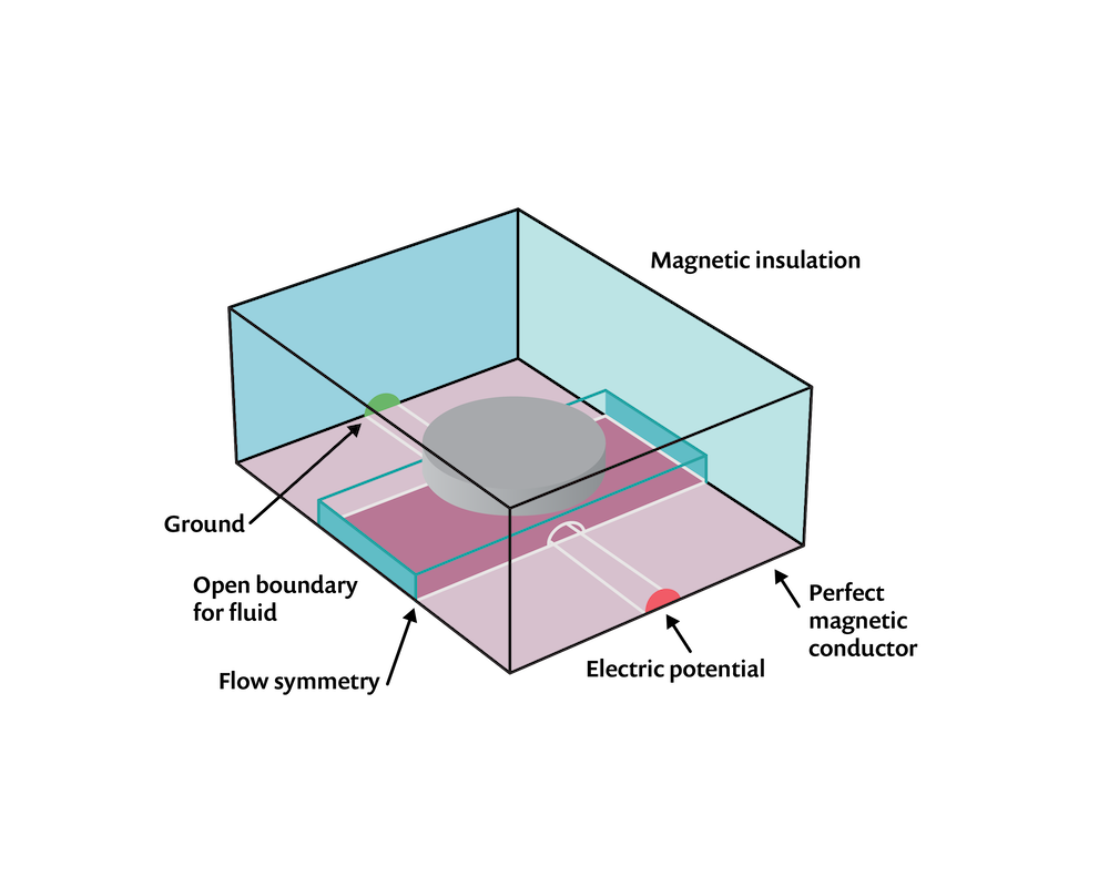
The computational domains and boundary conditions.
The flow will be driven by the volume force that arises due to the interaction of the electric currents in the fluid and the magnetic fields, which is \mathbf{F = J \times B} . The expression for this force is not built into the software, so here we will need to do a little bit of manual work. We need to find the built-in expressions for the components of the current flow and magnetic field, which we can do by looking at the Equation View and generating a report, as described in a Knowledge Base entry on implementing user-defined multiphysics couplings. These built-in expressions are used to define the volume force on the fluid, as shown in the screenshot below.
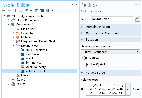
Screenshot showing the variables that compute the force components.
Lastly, to couple the computed velocity field back to the electromagnetic problem, use the Velocity (Lorentz Term) feature within the Magnetic and Electric Fields interface, as shown in the screenshot below. Note that the software automatically recognizes the fluid velocity field as an input to this feature. And that is all there is to it! The coupling between the two physics is now completely implemented.
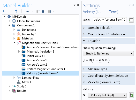
Screenshot showing how the velocity is coupled into the Magnetic and Electric Fields interface.
Meshing and Solving the MHD Problem
As far as the element meshing and element order, a significant concern here is the computational size of the model. Solving for the magnetic and electric fields in the fluid and surrounding domains is the most computationally expensive part of the model, and we would thus like to keep the total number of mesh elements in the whole model at a minimum. Based on some rules of thumb for linear static problems, we can say that having at least second-order elements is a good starting point. Thus, we will switch the discretization of the fluid flow to a P2+P2 discretization, meaning that both velocity and pressure are described with second-order base functions. The magnetic and electric fields are both described using second-order discretization. Since all fields are discretized to at least second order, the geometry shape order will thus automatically also be second order. A complete investigation of alternative mesh orders and mesh size is left as an exercise to the motivated reader.
When solving, the software will automatically use a so-called segregated approach that switches back and forth between determining the electromagnetic fields and the velocity field and calculates the linear subsystem for those fields, each with its own optimized iterative solver. As this multiphysics problem is inherently nonlinear, it is also generally helpful to be aware of the issues that might arise when solving such problems and how to address them, as discussed in this Knowledge Base entry on improving the convergence of nonlinear stationary models.
The results of this multiphysics analysis are shown in the plots below. We observe a distinct pumping effect: The applied voltage causes current to flow through the fluid, and as these charges move through the magnetic field, they experience a force, which is imparted to the fluid.
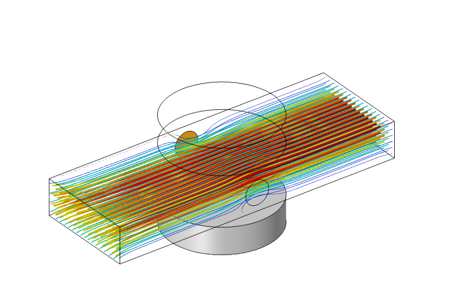
Results showing a fluid pumping due to the MHD multiphysics couplings.
Simplifying the MHD Model
What we’ve built up to this point is a model involving magnetic fields, electric currents, and fluid flow, and we have considered bidirectional couplings between all physics equations. That is, every physics phenomenon can affect all other physics phenomena. As it turns out, though, we do not need to do so for this particular case. Let’s next look at why this is and how it makes our model much simpler.
If we go back and look at all of the governing equations from earlier, we can see that there are only two equations that introduce couplings between the physics phenomena. There is the equation \mathbf{F = J \times B} that imposes a force on the fluid due to the current and magnetic field, and there is the equation for the total current in the fluid \mathbf{J} = \sigma \left( – \nabla V + \mathbf{v \times B}\right). The latter equation says that the current arises due to the imposed voltage boundary conditions as well as due to the movement of the conductive fluid through the magnetic field. However, if we assume that the former term is much larger than the latter (that is, – \nabla V \gg \mathbf{v \times B}), then we simplify the current equation to: \mathbf{J} = \sigma \left( – \nabla V \right) . This means that the fluid flow problem does not affect the current, which means that the flow equations can be solved entirely separately from the electromagnetic field equations. That is, we can first solve for the electromagnetic fields, and once those are known, use those fields as an input to the flow problem, which makes the problem unidirectionally coupled.
An additional simplification can be made. Strictly speaking, the magnetic field arises due to the magnets as well as the current flow. However, for the boundary conditions and material properties that we consider here, the magnetic field that arises due to the current flow is much smaller than the magnetic field due to the magnets. Thus, we can make the simplifying assumption that the magnetic field arises solely due to the magnets; that is, the currents do not produce a significant magnetic field. As a consequence, we can solve for the magnetic fields under the assumption of no currents and solve for the electric currents separately using the Magnetic Fields, No Currents and Electric Currents interfaces, respectively. These physics interfaces have a similar set of boundary and domain conditions to the ones previously discussed.
The Magnetic Fields, No Currents interface defines the equation \nabla \cdot \left( \mu_0 \mu_r \mathbf{H + B_r} \right) = 0, which is much less computationally expensive than the set of equations defined in the Magnetic and Electric Fields interface. Also, this equation can be solved independently of the electric currents.
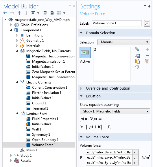
Screenshot showing the setup of the simplified model.
The screenshot above shows the setup of a new model after considering these simplifications. The expression for the volume force on the fluid will use different variable names, but otherwise, the model is very similar to before. Note that three different physics interfaces are solved in three separate study steps. The Magnetic Fields, No Currents and the Electric Currents interface equations can be solved separately and both must be solved prior to the Laminar Flow interface equations.
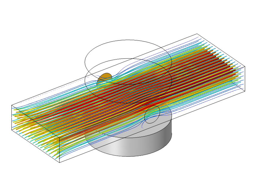
Results of the simplified MHD model.
The solution time will be greatly reduced when solving this simplified case, as compared to the fully coupled case, since the physics equations are solved separately and the software does not need to iterate between them. We can see from the results shown above that the solutions are almost identical to the previous, unsimplified case. Of course, these assumptions and simplifications that we’ve made do have their limitations, so it never hurts to check against a full model, but the power and flexibility of the COMSOL Multiphysics platform let us easily build both simplified and complete models, compare them, and modify them in whatever way we desire. Are you ready to get started with your own multiphysics modeling? Contact COMSOL here!
If you want to download the example model presented, it is available by clicking the button below.


Comments (9)
Trevor Munroe
January 7, 2021Walter, this is a very good blog. I have been running the tutorials varying the magnitude of Br. A pressure point constraint is needed at the outlet.
Walter Frei
January 7, 2021 COMSOL EmployeeHello Trevor,
The open boundary condition should be sufficient.
Nourhen Amdouni
May 10, 2021hey,can you please help me with the tutorial. I need it for a project as soon as possible and I am not that familiar with the software comsol. I don’t know exactly how to create the gemoetrical shapes nor am I able to deal with the equations needed. Thank you
Aashna Raj
February 12, 2021Hi Walter Frei
I have a similar flow problem in which the magnetic field is in a vertically upward direction due to a permanent magnet. Could you kindly help with the volume force components for this problem?
Francisco Saenz
February 16, 2021Hello Walter,
This is a great tutorial! I know that for this example, there is an external source of current and thus we have to include a ground and a terminal. I was wondering if the simulation of a liquid metal flow with no externally-applied currents would require the inclusion of a ground and a terminal…
Marcio NASCIMENTO
May 12, 2021Hi Walter. Can you help me? I have to simulate a rotation flow with an interior magnetic field and study the behavior of the fluid in such conditions. My initial conditions are such that I have V=V0*e_theta (azimuth) and a magnetic field described by a gaussian function B=B0*e_z (with B0=e^(-r^2/d^2) where d=1) on the inlet. My boundary conditions are V=V0*e_theta (azimuth) resulting in a rotating wall and B=0 (kind of a no-slip condition). Can you please help me?
Walter Frei
April 24, 2023 COMSOL EmployeeHello,
Please note that we have recently introduced a built-in Multiphysics coupling, between the Magnetic and Electric Fields interface and the Laminar Flow interface.
This Magnetohydrodynamics coupling replaces the first approach developed here, and is exemplified by the following benchmark model:
https://www.comsol.com/model/hartmann-boundary-layer-73451
as well as this example:
https://www.comsol.com/model/magnetohydrodynamics-pump-5907
Parsa Parsa
October 29, 2024Hello Walter, Thank you very much for providing this great model.
I want to work with a more complicated model accounting for ionization in a fluid/gas/plasma to further study the interactions of the ions together.
Do you have any insights on how I can proceed with that, or to use your model?
Thank you in advance.
Walter Frei
October 29, 2024 COMSOL EmployeeHello Parsa,
What you’re describing there may be more in the area of plasma modeling (https://www.comsol.com/plasma-module) and you might find these examples useful as starting points: https://www.comsol.com/models/plasma-module