
In many engineering applications involving conjugate heat transfer, such as designing heat exchangers and heat sinks, it’s important to calculate the heat transfer coefficient. Often determined with the aid of correlations and empirical relations, the heat transfer coefficient provides information about heat transfer between solids and fluids. In this blog post, we discuss and demonstrate how the COMSOL Multiphysics® software can be used to evaluate the heat transfer coefficient for plate geometries.
What Is the Heat Transfer Coefficient?
Let us consider a heated wall or surface over which a fluid is flowing. Heat transfer in the fluid is predominantly governed by convection. Similarly, convection is the primary mode of heat transport in the case of two fluids (through a solid surface), such as with heat exchangers. The rate at which heat transfer occurs in both cases is governed by a temperature difference and a proportionality coefficient called the heat transfer coefficient. The heat transfer coefficient is indicative of the effectiveness for the rate of heat transport through a domain between the surface and the fluid.
Mathematically, his the ratio of the heat flux at the wall to the temperature difference between the wall and fluid; i.e.,
(1)
where q^{\prime \prime} is the heat flux, T_wis the wall temperature, and T_\infty is the characteristic fluid temperature.
The characteristic fluid temperature can also be the external temperature far from the wall or the bulk temperature in tubes.
When the object is surrounded by an infinitely large volume of air, we assume that the air temperature far away from the object is a constant, known value. The heat transfer coefficient evaluated in this case is referred to as the external heat transfer coefficient.
With the above assumption, if we look closely at the wall (if the thickness of the wall is defined across the y direction, and y = 0 represents the surface/plane of the wall), it’s clear that the No Slip condition at the wall results in the formation of a stagnant, thin film of fluid. Therefore, heat transfer through the fluid immediately adjacent to the wall happens purely due to conduction.
This can be written mathematically (Ref. 1) as:
(2)
Here, k is the thermal conductivity of the fluid, with the Tderivative being evaluated in the fluid.
Combining equations (1) and (2), the heat transfer coefficient can be calculated as:
(3)
Calculating the Heat Transfer Coefficient in COMSOL Multiphysics®
Practically speaking, it is difficult to measure the temperature gradient at the wall. Additionally, it becomes essential to analyze a smart and computationally inexpensive approach for understanding the heat transfer at the wall. Therefore, nonanalytical ways of calculating the heat transfer coefficient are usually preferred.
One common approach is using convective correlations defined by the dimensionless Nusselt number. These correlations are available for various cases, including natural and forced convection as well as internal and external flows, and give fast results. However, this approach can only be used for regular geometric shapes, such as horizontal and vertical walls, cylinders, and spheres.
When complex shapes are involved, the heat transfer coefficient can instead be calculated by simulating the conjugate heat transfer phenomenon.
Let’s now discuss two different cases and approaches:
- Calculating the heat transfer coefficient in regular geometries (like a horizontal plate) using:
- Conjugate heat transfer analysis
- Convective correlations; i.e., without considering flow
- Calculating the heat transfer coefficient in irregular/complex geometries (like a corrugated plate)
Note that the flow regime is an important consideration because the heat transfer coefficient is dependent on the velocity. In both cases, a pragmatic condition, such as a fast flow in a blower system or an electronic chip cooling device, needs to be considered. This indicates that it is necessary to model the cases as a turbulent flow coupled with heat transport.
Example 1: Forced Convection and Flow Past a Horizontal Plate
Let’s consider the situation of modeling the flow past a horizontal flat plate with a length of 5 m, which is subjected to a constant and homogeneous heat flux of 10 W/m2. The plate is placed in an airflow with an average velocity of 0.5 m/s and temperature of 283 K. The figure below shows the schematic of the problem definition, including the velocity and temperature profiles for a laminar flow inside the momentum (say, \delta ) and thermal boundary layer (\delta {T}), respectively.


Schematics of laminar flow (top) and turbulent flow (bottom) past a horizontal plate.
Conjugate Heat Transfer Analysis
The numerical solution is obtained in COMSOL Multiphysics by using the Conjugate Heat Transfer interface, which couples the fluid flow and heat transfer phenomena. The velocity field and pressure are computed in the air domain, while the temperature is computed in the plate and in the air domain.
The temperature distribution inside the plate and fluid is shown in the figure below. The thermal and momentum boundary layers formed inside the fluid domain can be seen in the region that goes from the wall to 2 cm above the plate.
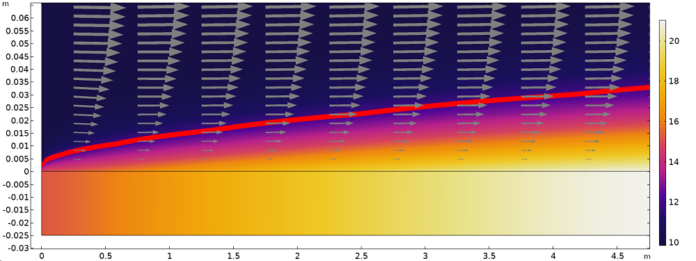
Temperature distribution (surface plot), isotherm at 11°C (red line), and velocity field (arrows) illustrating the thermal and momentum boundary layers next to the plate surface (anisotropic axis scale).
From the simulation results, it is possible to evaluate the heat flux using the corresponding predefined postprocessing variable. Dividing it by the temperature difference (T_w-T_\infty) gives the heat transfer coefficient (Eq. 3). The heat transfer coefficient along the plate obtained using the conjugate heat transfer analysis is plotted on a graph in a following section.
Heat Transfer Coefficient Based on Nusselt’s Number Correlations
The Nusselt number correlation for forced convection past a flat plate is available in literature (Ref. 1, for example).
In this second approach, the same model is solved without solving for flow; that is, using the heat transfer correlations. The computational domain is limited to the solid (plate). The heat loss from the hot plate to the cold fluid is defined using a Heat Flux boundary condition. This boundary condition contains an option to define the heat transfer coefficient using predefined Nusselt number correlations, as shown below. Note that this correlation is predefined in COMSOL Multiphysics.
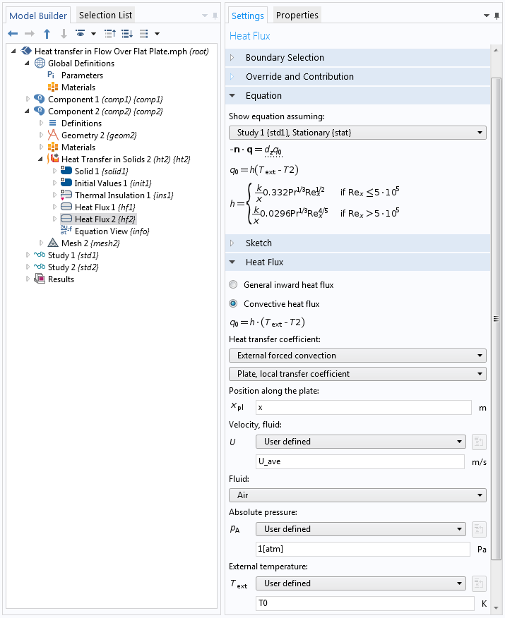
Settings for the Heat Flux boundary condition.
Using this approach only, the temperature distribution in the plate is computed. From the heat transfer coefficient defined in the Heat Flux boundary condition, it is possible to evaluate the heat flux at the plate surface, q=h\cdot(T_\infty-T).
Evaluating the Heat Transfer Coefficient
For both approaches described above, it is possible to evaluate the heat transfer coefficient along the plate. The figure below compares the heat flux estimated using the two approaches.
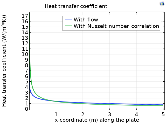
Comparison of the heat transfer coefficient along the flat plate estimated using a conjugate heat transfer simulation (blue line) and a Nusselt correlation (green line).
We can see that the value obtained from the Nusselt number correlation is in close agreement with the value obtained from the full conjugate heat transfer simulation.
A quantity of interest is the heat rates over the plate that are obtained in the two cases:
- Nusselt number correlation: 50 W/m
- Conjugate heat transfer: 49.884 W/m
For certain calculations, the approach based on Nusselt number correlations is able to predict the heat flux with good enough accuracy. Next, we examine a case with an uncommon shape, where the Nusselt number correlations are not easily available, and the only possible approach is to run a conjugate heat transfer simulation.
Example 2: Flow Past a Corrugated Horizontal Plate
Let’s consider a similar configuration as in the first case, except that the plate has a corrugated top surface. The figure below shows a schematic of the problem definition. In this model, the corrugations of the top plate are considered in one section of the geometry. The rest of the plate is flat.
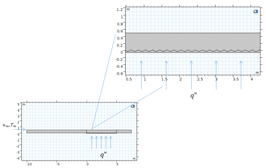
Schematic of the flow past a horizontal plate.
Here, the flow field close to the wall has recirculation zones that enhance the heat transfer rate. In the image below, we can see the temperature distribution and velocity streamlines.
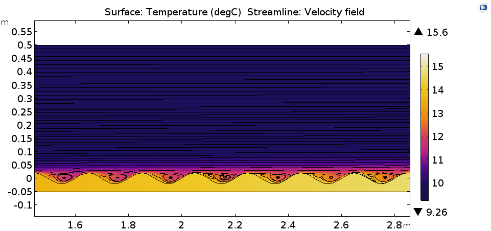
Temperature distribution in degrees Celsius (surface) and the velocity field (streamlines).
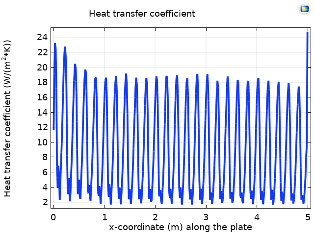
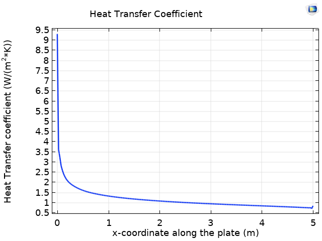
The left plot below shows the heat transfer coefficient along the length of the corrugated plate. With a geometry such as that of the wavy plate, the heat transfer coefficient is dependent on the temperature fields; velocity fields; and geometric parameters of the corrugations, such as the height. Hence, we can observe the enhanced heat transfer coefficient as compared to the flat plate (right image below).
Heat transfer coefficient along the corrugated plate (left) and along the flat plate (right).
While considering complex geometries containing corrugated surfaces, the conjugate heat transfer approach may be computationally expensive, and alternative approaches are desirable. A good approximation would be to reduce the geometric complexity by representing the surfaces as noncorrugated and extrapolating the heat transfer coefficient from this geometry of a corrugated plate, considering geometric parameters such as the corrugation height, flow velocity fields, and temperature variations on the surface. It is interesting to note that if the temperature is not truly isothermal or there is no constant heat flux, the heat transfer coefficient is still of interest within a given range for some geometries until the proximity to the initial configuration is maintained.
To check, we can consider a simple case wherein the heat transfer coefficients are calculated across velocity fields in the corrugated plate geometry. The data can be used to obtain an average heat transfer coefficient and can be extrapolated to the flat plate geometry model. The total heat loss from the surface, or the heat transfer coefficient obtained from flow simulations, can be investigated to understand the validity of the approximations.
Concluding Thoughts
In this blog post, we discussed how to calculate the heat transfer coefficient using two methods. With the conjugate heat transfer solution, you can use the built-in heat flux variables available in COMSOL Multiphysics. Using the Heat Flux boundary condition with Nusselt number correlations, you can simulate problems involving simple shapes. We also discussed how to reduce geometric complexities to obtain the heat transfer coefficient for complex geometries.
Next Steps
Learn more about the specialized features for modeling heat transfer in the COMSOL® software by clicking the button below.
Try the approaches discussed here in the following tutorials:
- Natural Convection Cooling of a Vacuum Flask
- Nonisothermal Turbulent Flow Over a Flat Plate
- Nonisothermal Laminar Flow in a Circular Tube
Reference
- A. Bejan et al., Heat Transfer Handbook, John Wiley & Sons, 2003.




Comments (2)
Anurag Agarwal
June 22, 2019Can you please share the COMSOL file.
Robert Gustavsson
December 4, 2020Thank you for this interesting subject. In section “Conjugate Heat Transfer Analysis” (below the picture) you say that Eq. 3 is used to calculate h. If you evaluate the heat transfer from predefined postprocessing variable – why is k used? Why is not Eq 1 used?