If you ever visit the extravagant dome within St. Paul’s Cathedral in London, be careful what you say. As Lord Rayleigh discovered circa 1878, the vaulted structure exhibits an interesting acoustics phenomenon: Whispers from one part of the dome can be clearly heard in other areas. Rayleigh called the effect a “whispering gallery”. Surprisingly, you can observe a similar effect in another field of science entirely: light waves traveling in an optical ring resonator.
What Is an Optical Ring Resonator?
Like optical filters, optical ring resonators are waveguide structures that allow only a narrow band of frequency. They can also be used to couple two optical waveguides in opposite directions. A typical optical ring resonator has two parts:
- A straight waveguide
- A ring waveguide
The waveguide cores are placed close together and light waves are coupled from one waveguide to the other.
An optical ring resonator (left) exhibits an effect similar to that of a whispering gallery (right), but with light waves instead of sound. Right: The whispering gallery at St. Paul’s Cathedral in London. Image by Femtoquake — Own work. Licensed under CC BY-SA 3.0, via Wikimedia Commons.
In the field of silicon photonics, optical ring resonators show potential as components for photonic integrated circuits. Due to the resonators’ high refractive index contrast, extremely small circuits can be produced. In addition, two or more optical ring resonators can be combined to develop high-order optical filters with compact size, minimal losses, and easy integration into existing networks. Other applications of optical ring resonators include tunable mechanical sensors, biosensors and spectroscopy, as well as quantum photon research.
In an optical ring resonator, light propagates around the loop and remains in the waveguides because of total internal reflection (TIR), a phenomenon in which light rays do not refract through the boundary of the medium they strike.
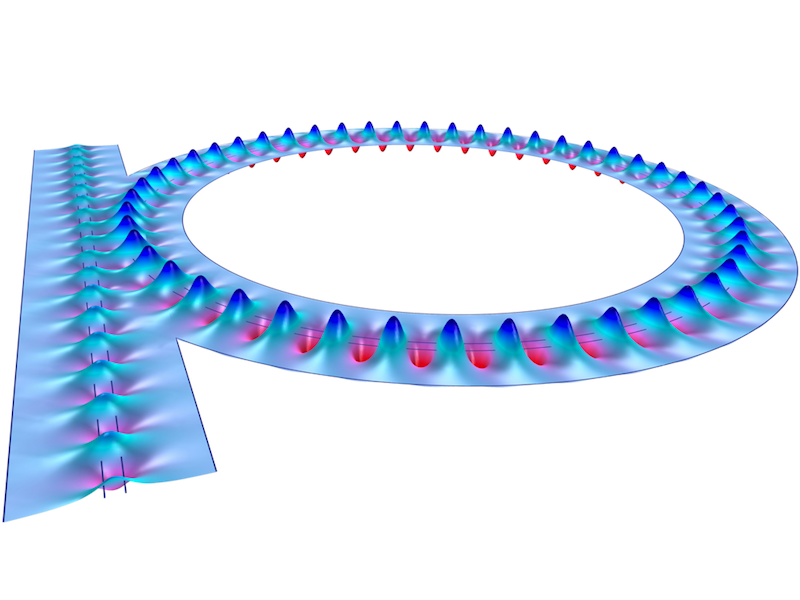
Light propagation in an optical ring resonator.
Since only a few wavelengths reach resonance within these loops, optical ring resonators are used as filters. The transmission loss of the resonator’s coupler balances the loss for the propagating wave, which is ideal for notch filters especially.
Simulating an Optical Ring Resonator in the COMSOL® Software
Wave optics modeling software is helpful for evaluating the spectral properties of optical ring resonators. For example, you can use the COMSOL Multiphysics® software and the add-on Wave Optics Module, which includes the predefined Electromagnetic Waves, Beam Envelopes interface. This interface is used to model optical wave propagation over many wavelengths and the results can help you evaluate the performance of an optical ring resonator as a notch filter.
The Electromagnetic Waves, Beam Envelopes interface is based on the beam envelopes method, a numerical method used to analyze the slowly varying electric field envelope for an optically large simulation. When compared to traditional optical analysis methods, the beam envelopes method doesn’t require a fine mesh to resolve the propagating waves. This makes it a computationally efficient option.

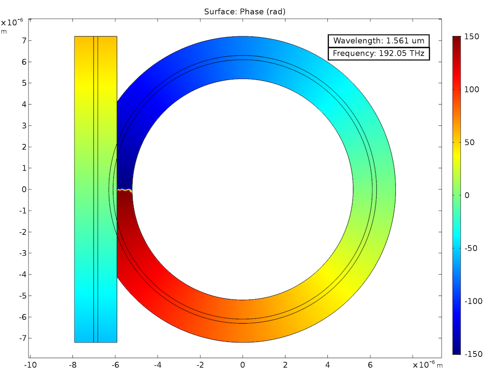
An optical ring resonator with a phase jump at the boundary between both waveguides (y = 0).
At the boundary between the straight and ring waveguides, there is a discontinuous phase approximation. By implementing a Field Continuity boundary condition, you can handle this phase discontinuity as well as that of the field envelope. The boundary condition makes it so the electric and magnetic fields have continuous tangential components at the boundary, even with a phase jump.
Evaluating the Simulation Results
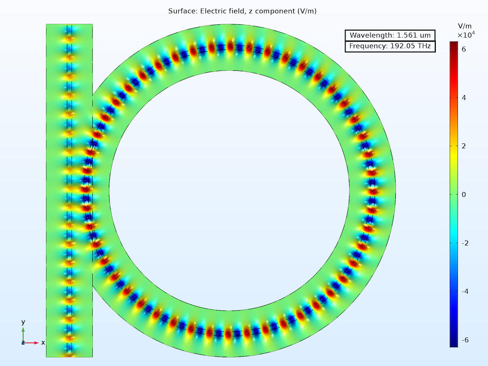
To calculate the spectral properties of the model, boundary-mode analyses and a frequency-domain study are run using the specialized modeling features for wave optics. Below, you can see a field plot of the resonant wavelength. These results show that when the field in the straight waveguide interferes with the field from the ring waveguide, they are out of phase; therefore, the outgoing field in the straight waveguide is almost zero. Since nearly no light is being transmitted from the straight waveguide, this optical ring resonator can be considered a well-designed notch filter.

You could test the parameters of the model to design an improved optical ring resonator that completely blocks light at the resonant wavelength — perhaps even by building an app to efficiently run multiple analyses.
Next Steps
Check out these related resources:
- Blog post on simulating silicon photonics applications
- Quick video demonstrating the beam envelopes method for wave optics modeling


Comments (7)
Madhusudan Mishra
December 31, 2018Hi Brianne,
It is really a good thing. Can you please help me how to work on add-drop ring (even more than one ring) resonator with COMSOL ? I really need this.
Brianne Costa
January 3, 2019 COMSOL EmployeeHello Madhusudan,
Thank you for your comment!
For questions related to your modeling, please contact our Support team.
Online Support Center: https://www.comsol.com/support
Email: support@comsol.com
MUHAMMAD SYAFIQ RAMLI
June 14, 2020Hi Brianne,
I’ve already done reading your blog post and it’s really a good read ! I’m able to learn much more now on the fundamental concept of the Optical Microring Resonator but somehow would you suggest me something (either webinar or forum post) regarding the 3D design implementation of the OMR?
Best regards.
Brianne Christopher
June 22, 2020 COMSOL EmployeeHi Muhammad,
Thank you!
We have a few technical papers and presentations on OMRs: https://www.comsol.com/search/?s=microring
You can also contact support@comsol.com for further assistance.
Best of luck!
Brianne
Houman Ghorbani
December 31, 2020Hi Brianne
Thanks for the useful blog!
Based on what I understood from the wave optics module, beam envelope is for frequency domain analysis. But for ring, one needs to see the response over a spectrum which I guess should use time dependent interface?
Brianne Christopher
January 11, 2021 COMSOL EmployeeHi Houman,
I am glad you found the post useful.
Please refer to the PDF documentation for the tutorial for more information, as well as support@comsol.com for any further assistance.
Best,
Brianne
Arghadeep Pal
March 11, 2021Hello Brianne,
I am trying to run the comsol program after increasing the dimensions of the ring resonator. But mostly I am getting a flat curve with no peaks and sometimes getting transmission greater than 1 which is not possible as it shall be normalized. I am very curious to know why this is happening?