Sometimes, at a certain point in the development of a device, you reach a catch-22. For instance, Fraunhofer Research Institution for Additive Manufacturing Technologies (IAPT) developed a heat sink design with an optimized topology, but the complex geometry made it difficult to manufacture. They found a solution in a type of additive manufacturing, but the method comes with its own restrictions. To find the best heat sink design, they needed a way to reconcile these issues…
Designing and Manufacturing a Topology-Optimized Heat Sink
Designing a heat sink for small electronic devices, like LEDs and computer chips, involves a delicate balance of design requirements: They need to be as small and as lightweight as possible, yet also offer extremely powerful cooling performance. When a conventional design is too heavy, we can use topology optimization to reduce the mass, while sacrificing as little cooling power as possible.

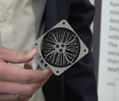
A 3D-printed, topology-optimized heat sink prototype.
Topology-optimized designs are both innovative and unintuitive. In this case, unintuitive is a positive, as it is a “way of finding function driven (‘organic’) designs that do not occur in a conventional design process,” says Fritz Lange, researcher at the Fraunhofer Research Institution for Additive Manufacturing Technologies (IAPT) in Hamburg, Germany. When it comes to heat sinks, topology optimization is useful for improving thermal performance and decreasing pressure drops.
This promising method, however, introduces another issue… In a topology optimization study, there is only one goal: finding the best design possible. The feasibility of production isn’t accounted for at all. Topology-optimized designs, therefore, often have complex geometries that are too difficult to produce with traditional manufacturing methods.
Now the question becomes: How do you manufacture a heat sink design when the geometry is extremely complex?
Enter an additive manufacturing process called selective laser melting (SLM). This process is well suited for producing topology-optimized heat sink designs, as the precision of a laser makes it possible to create intricate, detailed geometries. However, yet another issue arises: All types of 3D printing have some limit on the feature size. There are restrictions involved with SLM in order to ensure the final product is sound. For example, certain parts of the design may be too narrow to be printable. This is because the laser beam diameter can’t be larger than the diameter of the structure itself. In the case of a heat sink, the minimum wall thickness is limited by the radius of the laser beam.
Comparing Design and Manufacturing Approaches with COMSOL Multiphysics®
Considering these restrictions, researchers at Fraunhofer IAPT, along with researchers at the Institute of Laser and System Technologies at Hamburg University of Technology, set out to find the best possible active heat sink design for a laser diode.
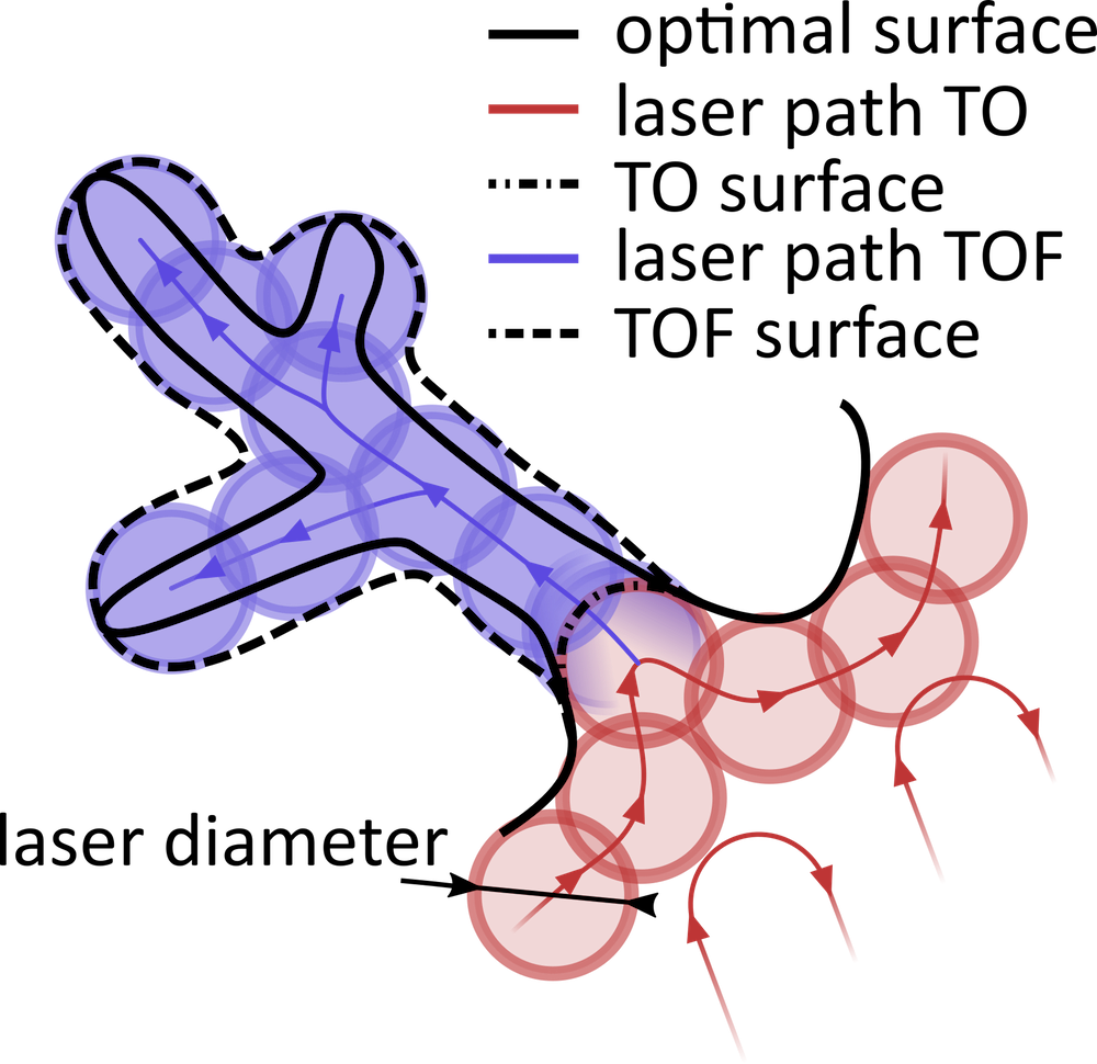
First off, in order to ensure optimal performance of the structure, they needed to develop a procedure to handle the thin, unprintable structures that violate the wall thickness restriction of the laser. The easy option is to simply avoid printing the small features (“TO surface” in the schematic below). However, this could reduce the cooling performance and effectively ruin the design. Another option, called forced edging, increases the size of the small features (“TOF surface” in the schematic below). The SLM machine is set so that the laser exposes the thin structures, creating thickened branches that increase the weight of the structure, but only cause a small loss in performance.

Laser paths for the different heat sink designs. The dashed black line illustrates forced edging. Image courtesy Fritz Lange.
To find a heat sink design with minimal loss in performance, the team compared heat sink designs developed with different optimization and manufacturing methods.
Numerical Simulation of Heat Sink Designs
The team compared two simulation methods:
- Parametric optimization
- Topology optimization
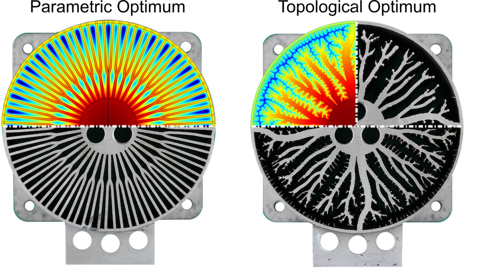
As you can see in the image below, to the left, the parametric optimization results in a lot of evenly sized and spaced fins, while the topology-optimized design has coral-like fin structures that decrease in width as they move outward.

The heat sink designs generated by parametric (left) and topology (right) optimization. Image courtesy Fritz Lange.
The COMSOL Multiphysics® software supports efficient and automatic calculation of sensitivities for arbitrary objective functions. This is crucial for gradient-based optimization, and thus all topology optimization. It used to be difficult to control the minimum feature sizes in topology optimization, but COMSOL Multiphysics version 5.4 supports Helmholtz filtering. This has a filter radius, which can be used to control the minimum feature size explicitly (see this previous blog post for details).
The parametric optimization study involves much fewer variables than a topology optimization study — in this case, six variables compared to the one for each finite element required for a topology study. This makes the parametric study much faster and it is also easier to find the global minimum. “This becomes more and more interesting when going to 3D and including fluid flow optimization,” Lange said.
Experimental Comparison
To both validate the optimization simulations and compare the different heat sink designs, the researchers turned to experiments. They compared three different designs:
- The topology-optimized heat sink with and without forced edging
- The parametric-optimized heat sink
- A conventional heat sink
Experiments showed that the conventional design offered the lowest thermal resistance, but with the greatest weight — which goes against the design specs of a small and lightweight design. The parametric optimum showed favorable results and could be ideal for designing heat sinks with simple geometries.

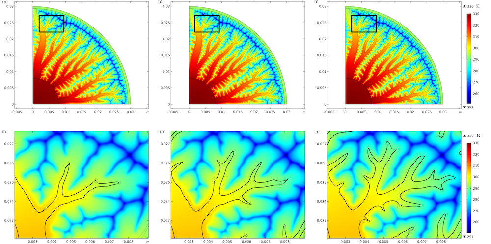
Simulation results showing the temperature distribution for different heat sink designs. Image courtesy Fritz Lange.
The results for the topology-optimized design were twofold. The design without forced edging had the best weight-related thermal resistance. The version with forced edging had lower thermal resistance, but the weighted thermal resistance was higher, compared to the design without the forced edging.
The team found the Optimization Module, an add-on to COMSOL Multiphysics, useful for performing both the parametric and topological optimization studies. “We were able to improve the performance of our components by a factor of about four,” said Lange.
Streamlining Optimization and Design Tasks with a Simulation Application
Looking for a way to make the optimization and design of AM heat sinks more efficient, Fraunhofer IAPT built a simulation application that can automate and customize the tasks involved.
The heat sink optimization application. Video courtesy Fraunhofer IAPT, via YouTube™ video community.
The simulation application, created using the Application Builder in COMSOL Multiphysics, is divided into four sections:
- Geometry
- Boundary
- Optimization
- Results
The Geometry section is used to define the design space with an option to use a heat sink template. There is also the ability to open a file to import a design that already exists.
Boundary is where the application user can define the hot and cold areas of the device. The Heat Source Domain option is used to define the heat source, while Heat Sink Domain is used to define the heat sink.
The Optimization section is where the application user calculates the optimal structure for the heat sink, and Results is where they can see and export the results. The application includes the option to save the results as an STL file, which means they are already in the required format for additive manufacturing!
Ongoing Research
The Fraunhofer team is continuing the research described in their paper by adding fluid flow optimization to their study in order to find the best optimum heat sink design. Fluid flow wasn’t considered initially because the aim of the project was to achieve the best possible comparability between the results.
Lange said he has already implemented fluid flow into the parametric optimization study, and that it is in progress for the topology optimization, which is a bit more complex.
Next Step
Read the related paper from the COMSOL Conference 2018 Lausanne: “Numerical Optimization of Active Heat Sinks Considering Restrictions of Selective Laser Melting“


Comments (2)
Khalid Hussain
May 3, 2019hi Brianne Christopher i need your help
kindly tell me how can we calculate the electric field strength at any point using FEM in COMSOL
after preparing model we apply specific voltage and then how we come to know that electric breakdown or electric discharge take place and at which level of voltage it is taking place
my email is hussain@ncepu.edu.cn
Brianne Christopher
November 25, 2019 COMSOL EmployeeHello Khalid,
Thank you for your comment.
For questions related to your modeling, please contact our Support team.
Online Support Center: https://www.comsol.com/support
Email: support@comsol.com
Best,
Brianne