
Three-phase power transformers are used in power grids worldwide for efficient electric power transmission. Though they offer significant advantages over single-phase transformers in terms of capacity, load balance, and efficiency, the computation of losses isn’t as straightforward. Using the COMSOL Multiphysics® software, we can reliably compute the losses in the core, coils, and carpentry, as well as important lumped parameters like primary and secondary inductance. The safety and reliability of transformers depend largely on how well the design is able to dissipate its losses. Negligence in this regard would warrant penalties and could result in large mishaps.
Power Transformers: An Introduction
The efficiency of electric power transmission from the source (such as a power generation plant) to the destination (such as the customer) is calculated by comparing the power generated and power received. For maximizing the transmission efficiency, energy losses during transmission need to be minimized. While transmitting power over long distances, this is achieved by reducing the currents flowing through the transmission network by increasing the voltage prior to transmission and decreasing it at the receiving end, generally in a substation.
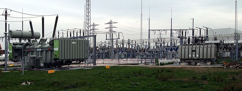
A power station with three-phase transformers in Bruchsal, Germany. Image by Ikar.us — Karlsruhe:Datei:Kändelweg NE.jpg, own work. Licensed under CC BY 3.0 DE, via Wikimedia Commons.
For AC power, this “stepping up” and “stepping down” can be done based on a surprisingly simple principle (thanks to Faraday) using a transformer, a succinct term for a device comprised of two coils and a piece of ferromagnetic material in its simplest form. Such a transformer uses a single alternating current and relies on a single alternating voltage, and is called a single-phase transformer. A common type of single-phase transformer is the E-core transformer.
How Do Three-Phase Transformers Work?
Three-phase transformers can be constructed by winding three pairs of coils to a single ferromagnetic core in a number of different configurations. The built-in Coils feature in COMSOL Multiphysics allows for flexible changing of coil configurations.
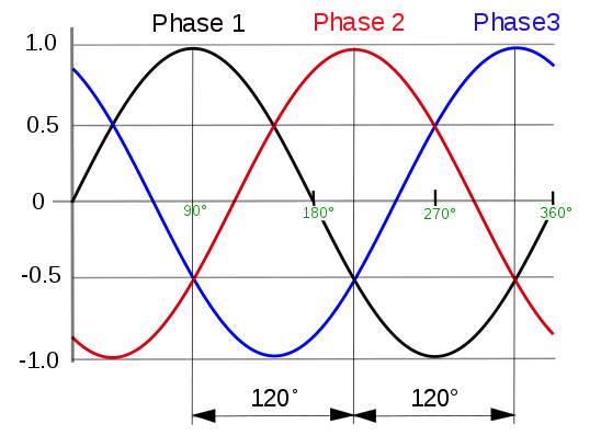
Three-phase waveform. Image in the public domain, via Wikimedia Commons.
Three-phase systems have a greater transmission capacity and are therefore more efficient than single-phase systems. In addition, the phase difference between conductors results in the voltage in each, reaching a peak at one third of a cycle after one of the other conductors and one third of a cycle before the remaining conductor, thus ensuring balanced loads.
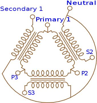
A delta-wye transformer configuration. Image by Gargoyle888 — Own work. Licensed under CC BY-SA 3.0, via Wikimedia Commons.
For large power distribution networks, however, transformers need to be further optimized to maximize efficiency and thus avoid possible failures that are often a result of high temperatures due to losses. Considering this, optimizing the design so that it is able to deal with the losses is one of the most crucial steps in order to build an efficient and reliable transformer. Under different working conditions, losses can occur in either of the different parts. Using multiphysics simulation, we can separately compute the losses in the coils, core, and carpentry of the transformer, thus using these inferences to improve the design and keep losses at a minimum.
How and Why Does a Power Transformer Incur Losses?
In a three-phase transformer, we can classify the losses in the different parts as follows:
- Core losses occur in the ferromagnetic core of the transformer.
- Core loss is commonly termed iron loss, as distinguished from copper loss, the loss in the coil windings.
- Most of the time, core losses are governed by hysteresis; that is, the lag of magnetization onto the applied magnetic field. Hysteresis losses are intrinsic to any magnetic iron and can be interpreted microscopically as the friction of the magnetic domain: It follows that the higher the magnetic field, the higher the hysteresis losses, and that these losses scale pretty linearly with frequency. In the open-circuit condition, these losses are maximum, as the maximum magnetic fields are induced in the core.
- Sometimes, the core may also experience losses because of eddy currents. These are generally smaller than hysteresis thanks to the usage of laminated iron, which minimizes eddy currents. Still, eddy current losses in the core may occur on the external surfaces, the sharp corners, or in some exposed parts, such as the clamping plates. This occurs mostly in short circuits or as a result of fast pulses. Calculating the eddy current losses of the core can often be done by treating that part of the core similarly as is done with carpentry.
- Coil losses, also called copper losses or I2R losses, occur due to Joule heating in the coil due to the electrical resistance of the conductor.
- In the case of DC currents, these losses can simply be calculated using Ohm’s law. However, when AC power is involved, the losses increase drastically due to the skin effect and proximity effect.
- Carpentry losses are losses in the metallic structures that support the transformer.
- These occur due to stray currents (eddy currents) that are induced into the carpentry.
Let us see how we can visualize these components and mathematically compute these losses using simulation. We will be simulating two of the most interesting scenarios, either of which often forms the limiting factors to predict losses. We will use 2D axisymmetric and 3D models in COMSOL Multiphysics for this computation. We will perform an open-circuit test by keeping the high-voltage winding open and applying a low voltage to the low-voltage end. We will also simulate a short-circuit test by shorting the low-voltage winding and applying a voltage to the high-voltage end to ensure a nominal current flowing through the circuit.
Modeling a Three-Phase Transformer in COMSOL Multiphysics®
Geometry, Materials, and Studies
For our 3D analyses, we model the entire geometry of the transformer, including the whole core and carpentry, while using homogenized coils. The 2D axisymmetric equivalent, on the other hand, illustrates a single phase with each coil turn explicitly modeled.
The three coils can be easily modeled with the built-in Coil feature and can be customized accordingly to fit a specific design.
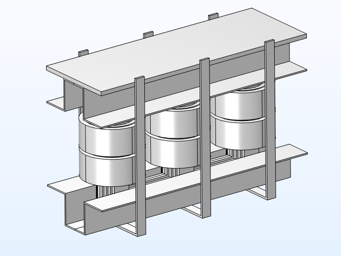
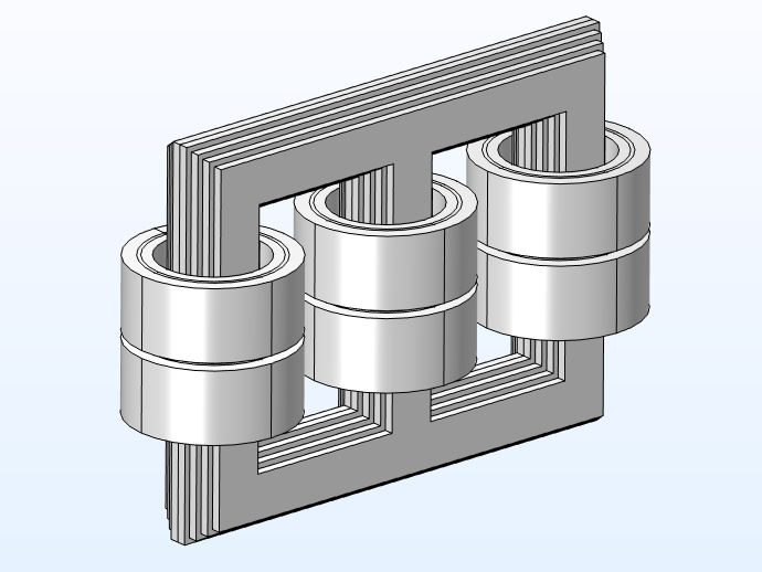
3D model geometry with and without the carpentry.
We select nonlossy iron (with a conductivity of 0.1) as the core material and copper for the coils. The carpentry is modeled using structural steel with an Impedance boundary condition. In the 2D axisymmetric model, we incorporate the individual conductor domains to understand the current density of the conductors.
The open-circuit test is performed only in 3D, as the open circuit deals mostly with retrieving the field in the core, while the short-circuit test is performed in both 2D axisymmetry and 3D, to analyze the large number of coils present and to capture the mechanical effects that do not appear in the 2D computation, respectively.
3D Model
For the open-circuit test, a nominal phase voltage is introduced in the primary coil, while the secondary coil is kept open (I = 0). Core losses are computed as below:
| Freq (Hz) | Core Losses (kW) | Core Losses (mur”) (kW) | Core Losses, Steinmetz Equation (kW) |
|---|---|---|---|
| 50.00 | 1.5971 | 1.4918 | 1.5663 |
As observed in the table, the simulated values are comparable to the values computed using mathematical formulas such as the Steinmetz equation.
Below is the magnetic flux density and the magnetization (saturation) of the core. As discussed above, both of these phenomena influence the losses incurred in the core.
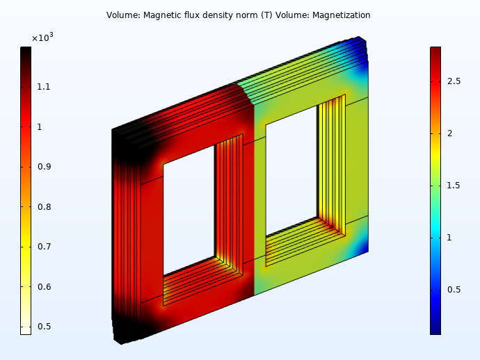
Saturation (left half) and magnetic flux density (right half) of the core.
To perform the short-circuit test in the 3D model, 12 coil feeds need to be changed; i.e., the coil excitation values need to be switched between the primary and secondary coils. To enable quick switching between these configurations, we make use of the methods functionality in COMSOL Multiphysics to automate this process. Using the short circuit test in 3D, we obtain the carpentry losses incurred. At 50 Hz, the carpentry loss is found to be 120 W.
2D Axisymmetric Model
We implement a short circuit on the primary and secondary coils in two separate studies to evaluate copper losses as well as secondary inductance. To enable the efficient switching of coil feeds while conducting each of the studies, we use the method functionality, which changes the coil excitation with a single click. The studies are run in the frequency domain.
Results
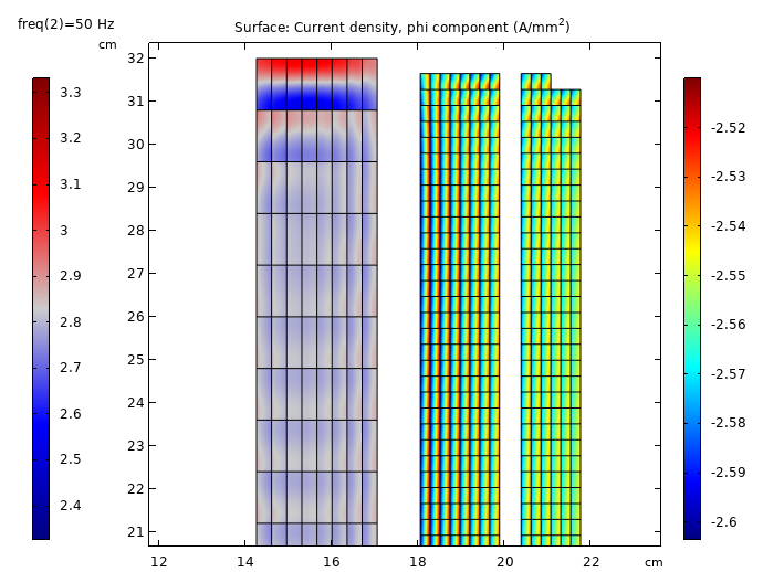
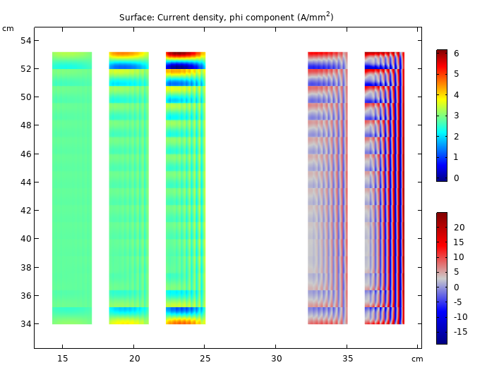
We can visualize the results in the plots below:
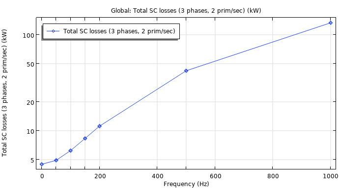
At 50 Hz, the copper loss is computed to be 5.5 kW.
Current density pattern. We see a skin effect develop in the conductors, indicating large differences in current density.
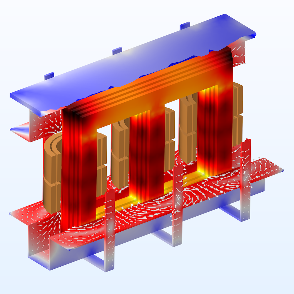
A three-phase transformer modeled in COMSOL Multiphysics.
Using multiphysics simulation, we can compute losses in the individual components of a three-phase power transformer with good accuracy. This is especially beneficial during the testing phase of R&D. Based on the simulation results, we can experiment with geometric parameters as well as other variables, such as coil thickness and core laminations, and design transformers with optimal performance and minimal losses.
Optimizing Real-World Transformer Designs with Multiphysics Simulation
For manufacturers of AC transformers, R&D of improved designs involves taking into account a number of different physical phenomena and the interactions between them. In this sense, designing highly efficient transformers is a true multiphysics problem.
One of the major multiphysics aspects influencing transformer designs is its heat dissipation. Evaluating transformers in terms of thermal performance contributes to the development of efficient cooling systems. Other factors that need to be analyzed are related to the mechanical integrity and material deformation both under static and dynamic excitations. Many resources about this can be found in our website and literature.
An example of a peculiar structural phenomenon caused by periodic excitation is the noise generated by a transformer, also known as transformer hum. This sound is a result of vibrations from different sources within the transformer, such as the transformer core and auxiliary fans and pumps used in the cooling system. The most important of these sources are the magnetostriction of the core and the Lorentz-force-induced vibration of the coils. Both these effects can be readily incorporated into the transformer model in the COMSOL® software.
While working on this problem, researchers at ABB Corporate Research Centre in Vasteras, Sweden, created a series of simulations and computational apps to calculate a number of parameters in the various transformer components.
Next Step
Download the model files using the button below and try out the model yourself:




Comments (0)