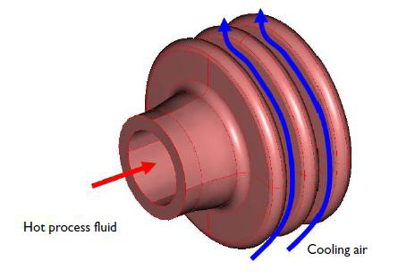
Chemical reaction fluids can be cooled using glass flanges. The reaction fluid is passed through the flange and the air surrounding the flange then serves as the coolant. Engineers looking to optimize the cooling performance of such flanges can look to simulation for help.

Cooling flanges’ operating principle.
A Heat Transfer Study
First off, the physics we want to analyze in this case is — you guessed it — heat transfer, involving both convection and conduction. Heat transfer will occur via convection to and from the surfaces of the flange, while the flange’s interior experiences conduction. In other words, the inside of the tube will be heated by the process fluid, and the flange then conducts the heat and transfers it into the air, in turn causing a convective flow due to buoyancy effects. The cooling performance of our flange will therefore depend on both convection and conduction.
To simplify the simulation we’ll want to analyze convection cooling using the heat transfer coefficient h. Since this describes the fluid-flow field influence and the convective fluxes, we don’t need to model the flow field. That’s excellent and all, but how do you determine what this convenient heat transfer coefficient is? In this particular model, we rely on external research data for the outer surface heat transfer coefficient, which was originally obtained through semi-empirical data for natural convection around a cylinder. For the tube-facing surface we can use a coefficient for forced convection in a tube.
Simulating the Temperature Field in a Cooling Flange
Let’s suppose our glass flange in question consists of a 4 mm thick pipe and 4 mm thick and 10 mm tall flanges, with a connecting pipe that has a 3 mm thick wall and an inner diameter of 16 mm. Note that during our simulation, the pipe diameter will vary while the other dimensions remain fixed. The cooling air is 298 K and the process fluid is 363 K.
Once we’ve set up and solved our cooling flange model we can analyze our results to determine how efficient it will be at cooling chemical reaction fluids.

|

|
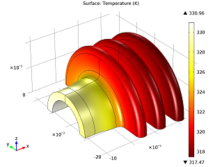
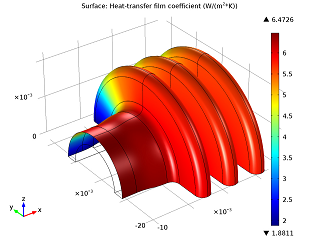
| Steady-state surface temperature of the flange. | Heat transfer coefficient for the flange’s outer walls. |
As you can see in the surface temperature plot above to the left, the tube surface temperature is about 13 K higher than the flange shoulders. From our model we can learn that the heat transfer from the outer surfaces of the flange is pretty efficient; there is a temperature difference of roughly 19 K between the outer flange surface and the air stream. The model to the right depicts the heat transfer film coefficient h for the outer walls. This visualizes that the coefficient decreases substantially along the vertical position of the outer boundary of the flange. We can calculate the flange’s total cooling power by integrating the total normal heat flux over the outer surfaces. Doing so gives us a value of 0.51 W, which corresponds to 1.02 W for the full geometry.
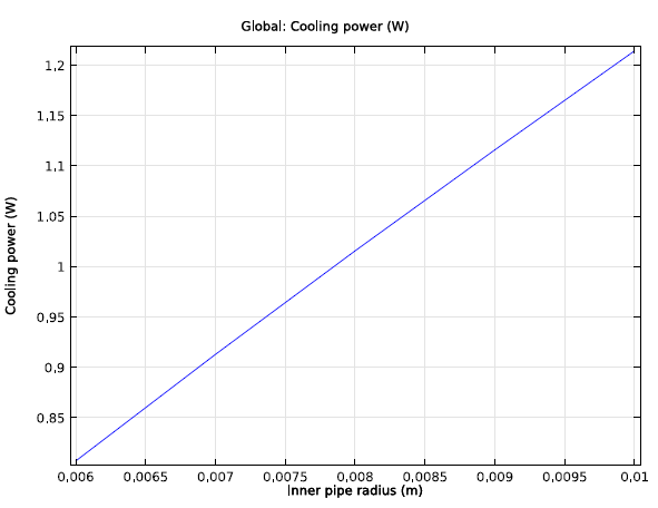
The surface temperature plot further gives light to an inefficiency in our current flange design. When it enters the flange the process fluid is 363 K, while the inner surface of the pipe is only 32 K lower. Increasing the tube diameter would improve the heat transfer here, which we perform in a second stage of our modeling by varying the pipe’s diameter, but keeping all other factors constant. By plotting the global cooling power as a function of the inner pipe radius, we can now analyze how altering the radius impacts the performance of our cooling flange.

Total cooling power as a function of the inner pipe radius.


Comments (0)