
Spectroscopic imaging has been used for decades to map the chemical composition of material surfaces with atomic-scale resolution. In order to achieve adequate chemical specificity and spatial resolution during imaging, both the material sample and the imaging system are placed under high or ultra-high vacuum (UHV). In practice, materials are often used outside of vacuum environments and therefore it is also necessary to evaluate their surface properties at higher or ambient pressure. Differential pumping is the key to designing vacuum systems for spectroscopic imaging where the sample can be held at higher pressure while the spectrometer is operated at the lower pressures (or high vacuum) required to achieve good image quality. This blog post will explore vacuum system design for ambient pressure spectroscopic imaging and how molecular flow simulations can be used to design and optimize differentially pumped vacuum systems.
Ambient Pressure X-Ray Photoelectron Spectroscopy
X-ray photoelectron spectroscopy (XPS) is a prime example of an imaging technique that has been used extensively in R&D to characterize the chemical and electronic properties at the surface of a material. In XPS, x-rays interact within the first 10 nm of a material sample to eject electrons from their atomic orbitals via the photoelectric effect. Electrons are focused toward an energy analyzer and detector in the XPS system, as shown in Figure 1.
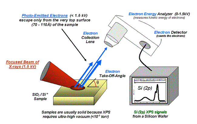
Figure 1. General operating principle behind XPS. Image attribution: Bvcrist.
The binding energy of each detected electron is determined and then recorded to generate a characteristic plot that corresponds to a particular chemical element, shown more clearly in Figure 2.
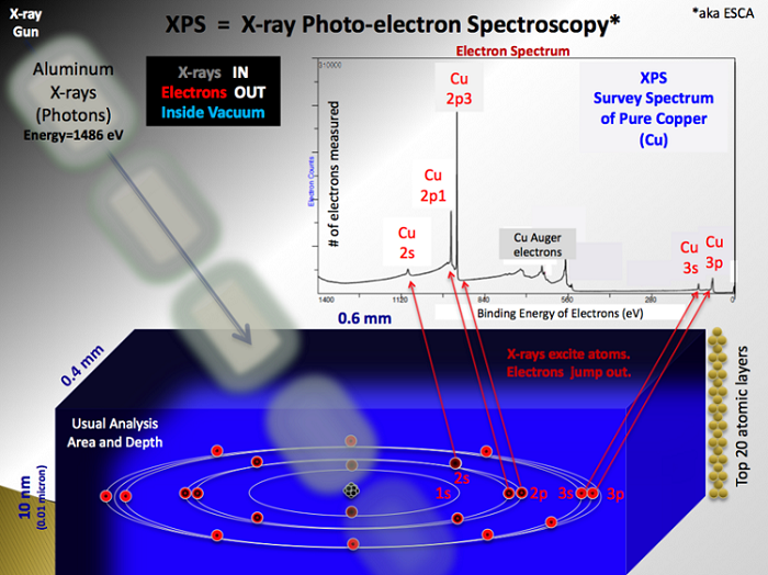
Figure 2. Characteristic plot shows the number of electrons with a given binding energy and is used to identify a particular chemical element. Image attribution: Bvcrist.
A drawback of XPS is that it requires the sample and system to be held at high vacuum or UHV. Ambient pressure XPS (APXPS) was developed initially in the early 1970s at Uppsala University to enable the evaluation of material surfaces at higher pressure while the XPS system components remain under high vacuum. Since then, and particularly in the last ten years, the technology has experienced tremendous growth with the number of publications and instrument installations experiencing a five-fold increase.
In great part, APXPS was enabled by designing multistage differentially pumped vacuum systems that allow the detector to continue operating at UHV while the sample itself can be exposed to higher pressures. Differential pumping through small apertures in combination with electrostatic electron focusing has been used successfully in many modern designs, an example is shown in Figure 3.
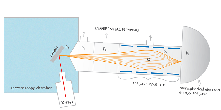
Figure 3. A common scheme for implementing APXPS using differential pumping and electrostatic focusing. Figure not
drawn to scale.
Commercial APXPS systems became available during the past ten years and use a range of methods including the basic scheme shown above.
Molecular Flow Simulation of Differential Pumping
When designing complex systems, such as those for APXPS that require differentially pumped vacuum and electrostatic electron focusing, it is generally good practice to model the system first. Simulation results can serve as a guide in early stage design decisions and throughout the system optimization process.
A model of molecular flow in a differentially pumped vacuum system is already available in the COMSOL Model Gallery. It is possible to expand upon this model to create more complex vacuum system models for your own application. In the model, two vacuum chambers are connected by a small tube. Chamber a is held at a higher steady state pressure relative to chamber b. Chamber b is connected directly to a vacuum pump. A schematic illustrating the concept and the actual model geometry in the COMSOL environment are shown in Figures 4 and 5, respectively.
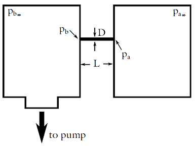
Figure 4. Schematic showing the concept of differential pumping.
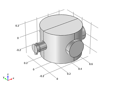
Figure 5. Model geometry of a differentially pumped vacuum system in COMSOL. The model is available in the Model Gallery.
The COMSOL model geometry includes the entirety of the high vacuum chamber, connecting tube, and port to a vacuum pump. Boundary conditions are applied such that modeling the high pressure chamber (chamber a) is not necessary.
The model is set up and solved using two different methods. In the first method, method 1, an outgassing wall boundary condition is applied to the outlet of the tube on the side of the high vacuum chamber. The tube is not included in the model in this case. The boundary condition represents the flow coming out of the tube from the low vacuum chamber. The mass flow rate in the tube is determined from an analytical expression developed by Gallis, et al. that assumes isothermal flow.
In the second method for solving the model, the Free Molecular Flow interface in the Molecular Flow Module, an add-on product to COMSOL Multiphysics, is used to solve for the mass flow rate and inlet/outlet pressure of the tube. For this case, the tube is included when solving the model. At the high pressure end of the tube, the reservoir boundary condition is used to set the steady state pressure. In both methods, the vacuum pump operates at constant speed. The results are compared with those obtained from the analytical expression used in the first method.
Comparing Methods for Simulating Molecular Flow
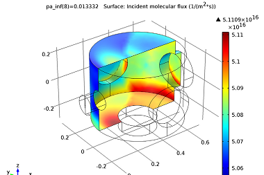
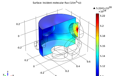
The incident molecular flux is plotted on the surface of the high vacuum chamber where the pressure in the low vacuum chamber is 0.1 mTorr. In Figure 6, flow through the tube was modeled using the expressions from Gallis et al., whereas in Figure 7, flow was modeled using the Free Molecular Flow interface and the reservoir boundary condition.
The distribution of the molecular flux on the surface is different where significant molecular beaming effects are observed in Figure 7 on the wall across from the tube outlet. In using an analytical expression to obtain the results in Figure 6, diffuse emission was assumed at the outlet while in practice molecular beaming will occur.
Although it is possible to resolve differences between the two approaches using COMSOL, it was found that using the expression in the first method is a reasonably accurate approach that applies to the full range of Knudsen numbers and flow regimes. In the molecular flow regime where molecular beaming is most pronounced, the mass flow rate into the high vacuum chamber was computed using methods 1 and 2 to be 1.63 x 10⁻¹¹ kg/s and 1.65 x 10⁻¹¹ kg/s, respectively. The number density along the inside of the tube was also determined using both methods and is compared in Figure 8.
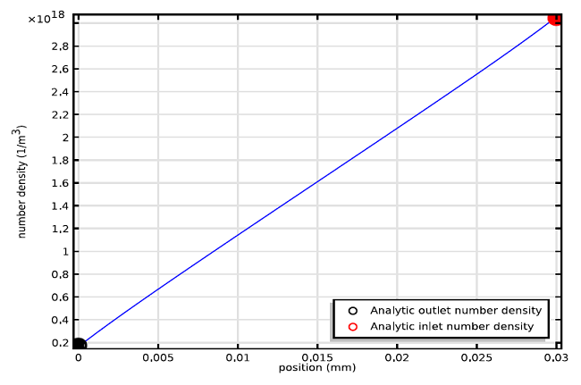
Figure 8. Number density was determined along the inside of the tube. Discrete black and red data points were
determined analytically using method 1. The blue line was determined using method 2.
The individual data points determined analytically at the tube inlet and outlet show excellent agreement with the linear plot obtained using method 2. Therefore the analytic approach used in the first method can be used reliably to reduce computational complexity and solution time when modeling differentially pumped vacuum systems in COMSOL.
Further Reading
- Download the Differential Pumping model and documentation from the Model Gallery.
- See the Gallis et al. paper “Direct simulation Monte Carlo-based expressions for the gas mass flow rate and pressure profile in a microscale tube” for a detailed explanation of the analytical expression referred to in this post.
- Read “Investigation of solid/vapor interfaces using ambient pressure X-ray photoelectron spectroscopy” by Starr et al. for more information about Ambient Pressure XPS.




Comments (1)
Leon Doigh
September 20, 2025in webminar called “Simulating Vacuum System Designs with COMSOL Multiphysics”
it is mentioned that boundary condition in the angular coefficient method relate between incoming G and outgoing J flux for Pump J<G
Will you please explain to me how can a pump out flux be smaller than its incoming flux. because this looks illogical in my modest point of view