
You might think you’re a smooth driver — but your engine probably doesn’t. Everyday obstructions like traffic lights and changing speed limits mean that the power demands of a car drivetrain vary rapidly. Since we expect new technologies like hybrid or electric vehicles to match the performance of existing cars in responding instantly to the demands of our right foot, designers need to make sure that this is possible and safe. One part of this involves modeling batteries.
Power Demands During a Drive Cycle
A drive cycle is a typical performance test for a car: get in, start the engine, accelerate, drive at speed, brake, stop, and repeat. In this animation, we see the electrical current requirements placed on the battery of a hybrid electric vehicle during such a cycle:
Drive cycle current for a hybrid vehicle. Positive spikes represent power provided to the engine or drivetrain; negative spikes are power recovery from the engine or from braking.
To start, there’s a big positive spike as the internal combustion engine is started by using energy stored in the battery. The battery also tops up some power demands for acceleration. Once the car is up to speed, some battery power can be recovered from the engine, so the battery current becomes negative. At about 110 seconds, we see some sharp negative spikes thanks to energy recovery as the car brakes and comes to a stop. The internal combustion engine is then switched off at idle and restarted for the cycle to be repeated.
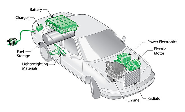
“Plug-in hybrid electric vehicle (PHEV) diagram” by Matt Howard – Plug-in hybrid electric vehicle (PHEV) diagram. Uploaded by Pieter Kuiper. Licensed under CC BY-SA 2.0 via Wikimedia Commons.
As you can see, the current demands on the battery are by no means smooth! Rapid changes in the current drawn from a battery, or even from energy recovery as in a hybrid vehicle, can cause changes in the driving voltage as well as heating. While a battery can be run at a high power output (or input) for a short time, it’s likely to heat up more quickly at higher current loads. The battery management system needs to ensure that the battery can recover rather than overheat. The user shouldn’t know that this is happening, though — no driver wants the available power to vary, apparently randomly, due to the behind-the-scenes condition of the battery.
How to Model a Lithium-Ion Battery
Modeling the battery under a range of charge and discharge rates, as well as under realistic drive cycles for normal road conditions, enables engineers to identify the demands that can be placed on the battery in a safe manner.
A physical model of a Li-ion battery must incorporate the essential physics that determine the relation between the current and voltage on the cell. This includes:
- Electrode kinetics of lithium insertion in porous electrode materials
- The concentrated species theory for charge and mass transfer by Li+ and other ions in the electrolyte
- Mass transport of lithium in the electrode materials
- The charge transfer in solid conductors, such as current collectors or porous electrodes
This may sound like a lot of equations, but fortunately they can be put together using the COMSOL Multiphysics Battery Design Module, by the combination of a predefined Lithium-Ion Battery interface and a Heat Transfer in Solids interface to predict the temperature profile in the battery.
Once the physical equations are defined, they can be loaded with a certain current or voltage. We might start by modeling charge and discharge at a specific rate. Usually, rates are measured in units of C, where 1 C means (dis)charge of 100% of the battery capacity in one hour. As you can see in the drive cycle current above, peak demands may be as high as 20 C, but in practice, these rates are not required for very long. With an experimentally measured profile of battery current load versus time from a real test, the typical duration and distribution of current spikes can be captured.
First, let’s look at the response of the battery state-of-charge. The state-of-charge is a measurement of the available charge remaining in the battery. When a rechargeable battery is deployed in a hybrid vehicle or a similar application with varying power demands, a battery management system (BMS) is used to monitor the battery condition and determine the currents that can be supplied.
There are a number of different methods to infer the state-of-charge (SOC) from measurable circuit quantities. One way is the “coulombic” method that integrates the cell current. In hybrid vehicle management, it is also possible to measure the SOC and allowed operating voltage window for the battery, according to a manufacturer’s specification. A physical model of a battery enables a comparison between the real state-of-charge of the cell, based on the amount of lithium in each electrode, with experimental SOC measurements according to different protocols. This can improve the engineer’s understanding of dynamic battery response, extraction of information from the battery, and safe operating limits.
The coulombic state-of-charge during the drive cycle is plotted below:
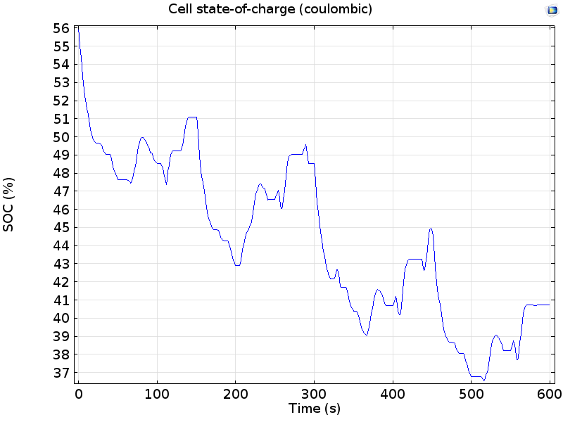
Cell state-of-charge during the drive cycle, from a coulombic (current integral) method.
In these results we can see that the battery begins at 56% SOC and begins to discharge as power is consumed by the drivetrain during the first cycle. The SOC increases when power is returned to the battery by energy recovery in the hybrid vehicle; however, the SOC continues to decrease overall because each repeat of the drive cycle consumes more power than it recovers.
The relation of current to state-of-charge is simple to determine, but it tells us nothing about how much power can be extracted from the battery. A theoretically ideal battery will always maintain its equilibrium voltage, no matter how quickly it is charged or discharged, and so the power is simply the product of the cell voltage with the current. In practice, though, resistance, kinetics, and mass transfer cause batteries to become polarized, meaning that a proportion of the open circuit voltage, as recorded at zero current, is lost in allowing a certain amount of current to flow.
In the limit of very high current, depletion may occur; the battery simply runs out of material to react. All of these represent a portion of the chemical energy from the battery reactions that is used up in delivering current — it can’t be used to deliver mechanical work, which results in a loss of efficiency.
To assess these effects, let’s look at the cell voltage during the drive cycle:
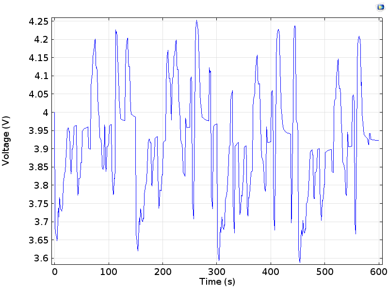
Voltage on a cell during a drive cycle, oscillating about an equilibrium (open circuit) voltage close to 4 V.
We can see that the cell voltage oscillates about the equilibrium cell voltage (close to 4 V) as charge is drawn from the battery, or returned while charging. Below, we plot the difference between this equilibrium cell voltage, as measured for the state-of-charge of the cell, and the measured cell voltage. This shows the variation of the cell polarization as the current load is changed:
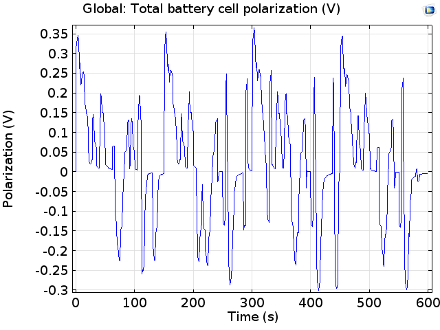
Polarization of the cell during the drive cycle. Positive polarization is for discharge.
The magnitude of the cell polarization is less than 0.4 V at all times, whereas the cell voltage is in the range of 4 V. This suggests that the losses are quite modest compared to the operating power. This operating power can also be plotted:
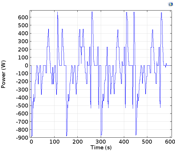
Note that this is the power from a single cell in a battery pack that in practice might contain many cells connected together, usually in a mixed series or parallel configuration. The powers of < 1 kW here would not get far on their own in driving a car! A standard engine might deliver about 75 kW.
From the polarization, we can assess the amount of power lost due to charge transfer resistance, electrode kinetics, and mass transfer in the cell:
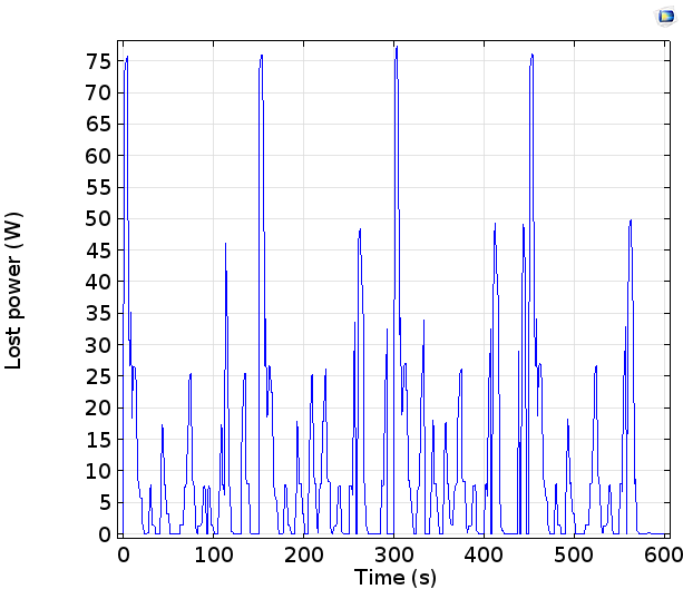
We can see that the power losses remain less than 0.1 kW, even for peak power delivery close to 1 kW. This means that the losses, while not negligible, give only modest limitations in the efficiency of power delivery or uptake, under the currents studied.
This lost power is released as heat, which can also cause a temperature increase. A very important safety check for batteries is their temperature. Thermal runaway in lithium-ion batteries can cause fires, so avoiding overheating is an essential concern for any battery system, particularly if operating at high power or with unpredictable loading. Even more, higher temperatures cause accelerated deterioration and aging of the battery on repeated charging and discharging, especially when the temperature exceeds 50°C for a standard lithium-ion battery. In the long term, this will reduce the energy capacity of the battery and lower the maximum deliverable power.
By coupling the lithium-ion model to a heat transfer model of the cell, it is possible to predict the transient temperature. The coupled model includes heat dissipation from the cell by convective cooling, heat evolution due to resistive heating and chemical reactions, and temperature dependence of electrical conductivity and kinetic rate constants.
The temperature profile is shown below for two different points in the cell:
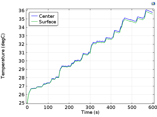
Predicted temperature during the drive cycle at two points in the battery.
The results are mixed! Encouragingly, the battery heats relatively uniformly; the temperature difference between the cell center and cell surface is negligible. This is normally best to avoid damage due to thermal stresses associated with uneven heating. Also, the overall temperature increase through the 10-minute drive cycle is modest, increasing from 25°C to 35°C. This keeps the temperature within a regime where we expect the rate of battery deterioration to be slow.
One problem seems to be that the battery temperature is continuing to increase. If this trend continues indefinitely, then the battery would likely overheat after a longer period of continuous operation. Clearly, this is not acceptable — perhaps the designer might consider a more aggressive cooling system, but this will also come with its own demands for weight and power consumption in the vehicle.
Perspective on Electric Vehicles
The example we’ve talked about so far concerns a hybrid vehicle in which a battery is allied with an internal combustion engine. What would be the differences for a purely electric vehicle?
A traditional internal combustion engine for a normal-size car runs constantly at speeds roughly between about 1000 and 4000 rpm. If the engine is stopped, a significant input of energy from the battery is needed to restart it. While the engine is running, the drivetrain uses a transmission system involving gears and either a manual clutch or an automatic gearbox with a torque convertor to allow the power delivery to the wheels to change over a significant range without the engine speed needing to accelerate and slow to the same degree. Even so, engine speed can only accelerate at a finite rate as more fuel is supplied.
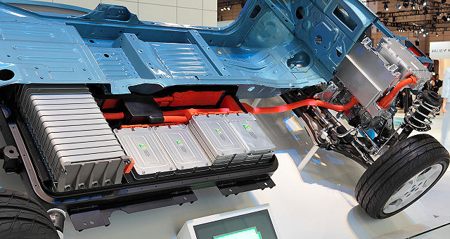
The drivetrain of an electric vehicle. “Nissan Leaf 012” by Tennen-Gas – Own work. Licensed under CC BY-SA 3.0 via Wikimedia Commons.
For an electric vehicle, the situation is different. Because a battery can idle, delivering no power and without needing to be turned off, power can be supplied to the wheels directly without an interruption through a transmission. Equally, the power drawn from a battery can be changed very quickly. This instant torque delivery gives some brisk 0 – 60 mph times (under 10 seconds) and a fun driving experience, according to some recent road testers.
All of this excitement comes at a cost. When the battery is the sole energy source, the energy demands and the rate of variation in power delivery become even higher than in the hybrid case. Building a battery system that can actually deliver this power repeatedly and without overheating or deteriorating is a major outstanding challenge for the next generation of electric vehicles. Multiphysics modeling of batteries, considering both electrochemistry and heat transfer properties, can help determine where improvement is necessary and how gains might be best achieved.
Find Out More
- Download the “1D Li-Ion Battery Model for Monitoring Drive Cycles” tutorial model
- Read more about the Battery Design Module
- White Paper: “Modeling the Lithium-Ion Battery“


Comments (0)