
Modifying an imported mesh can prove useful in certain scenarios. In this blog post, we will discuss the functionality for editing, repairing, and connecting imported surface meshes in the COMSOL Multiphysics® software. We will compare the results of different operations, introduce some use cases, and point to existing tutorials and other relevant resources for learning more.
Editor’s note: The original version of this post was published on February 25, 2021. It has since been updated to reflect new features and functionality in version 6.0 of the COMSOL Multiphysics® software.
Formats for Importing Surface Meshes
Both geometry and mesh import in COMSOL Multiphysics support the import of 3D surface mesh formats. The following three formats are the most common and are all supported in the software:
- STL
- 3MF
- PLY
Since the use of these formats doesn’t originate from finite element analysis (FEA) simulations, but rather from applications such as laser scanning and 3D printing, generating surface meshes of good quality has historically not been important. These formats often contain elements of poor quality by which we, from a simulation perspective, mean:
- Triangles with very large or very small angles
- Triangles that differ very much in size
- Problematic areas such as holes, thin spikes, or other irregularities in the shape that are unwanted
For imported meshes of poor quality, repairing and editing is often needed, as well as the remeshing of surfaces to smooth over small irregularities. We’ll discuss this in more detail below.
Different Ways of Editing Surface Meshes
There are several operations for editing imported surface meshes:
- To create entities, you can use:
- Create Vertices
- Create Edges
- Create Faces
- Create Domains
- Fill Holes
- To intersect, partition, join, or delete entities, you can use:
- Union
- Intersect with Plane (3D)
- Intersect with Line (2D)
- Partition with Ball
- Partition with Box
- Partition with Cylinder
- Partition by Expression
- Join Entities
- Delete Entities
- To generate and modify meshes, you can use:
- Free Quad
- Free Triangular
- Free Tetrahedral
- Adapt
- Refine
Let’s look into some use cases and the differences between the operation categories.
Refining vs. Adapting a Surface Mesh
To refine an imported mesh, you can use the Refine operation. If you’re looking for an operation that also supports the coarsening of a mesh, you can use the Adapt and Free Triangular operations. All three of these operations place new or moved mesh vertices on a curved surface approximation of the input mesh. This means that if the output mesh is finer than the input mesh, curved surfaces will typically be represented more smoothly, as seen in the example below. To learn more about how new and moved mesh vertices are placed on curved surfaces, read the blog post “How to Refine and Adapt Imported Meshes”.
To explain the difference between refining, adapting, and remeshing a surface mesh, we’ll use the following coarse surface mesh of a unit sphere as an example.
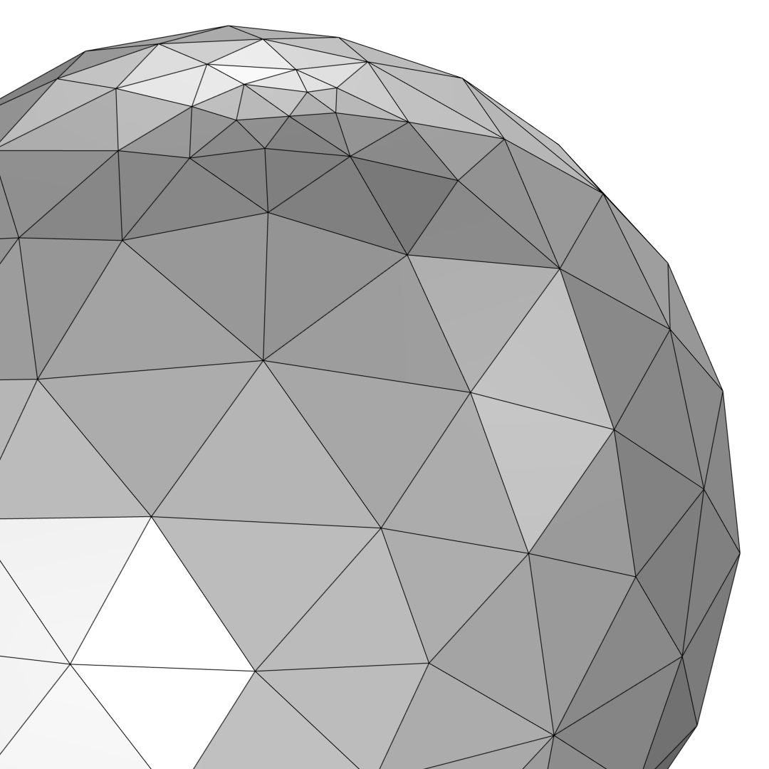
Coarse triangular mesh of a unit sphere. The mesh is slightly finer at the top of the sphere.
A coarse mesh of the unit sphere is imported into three different models so that we can compare the results of the Refine, Adapt, and Free Triangular operations side by side. The element size of the largest triangles in the imported mesh is about 0.6 m. For the Refine operation, we can specify that the elements should be refined once. This will replace each triangle with four smaller triangles. In the Adapt operation, if you select None from the Solution list and Absolute from the Type of expression list, you can specify a target element size (in this case, 0.3 m) that will guide the adaptation. For the Free Triangular operation, we can set the maximum element size; in this example, this is set to 0.3 m. When running this mesh operation, a smooth geometric surface is created in the background on which the new mesh is placed (this step is not visible to users).
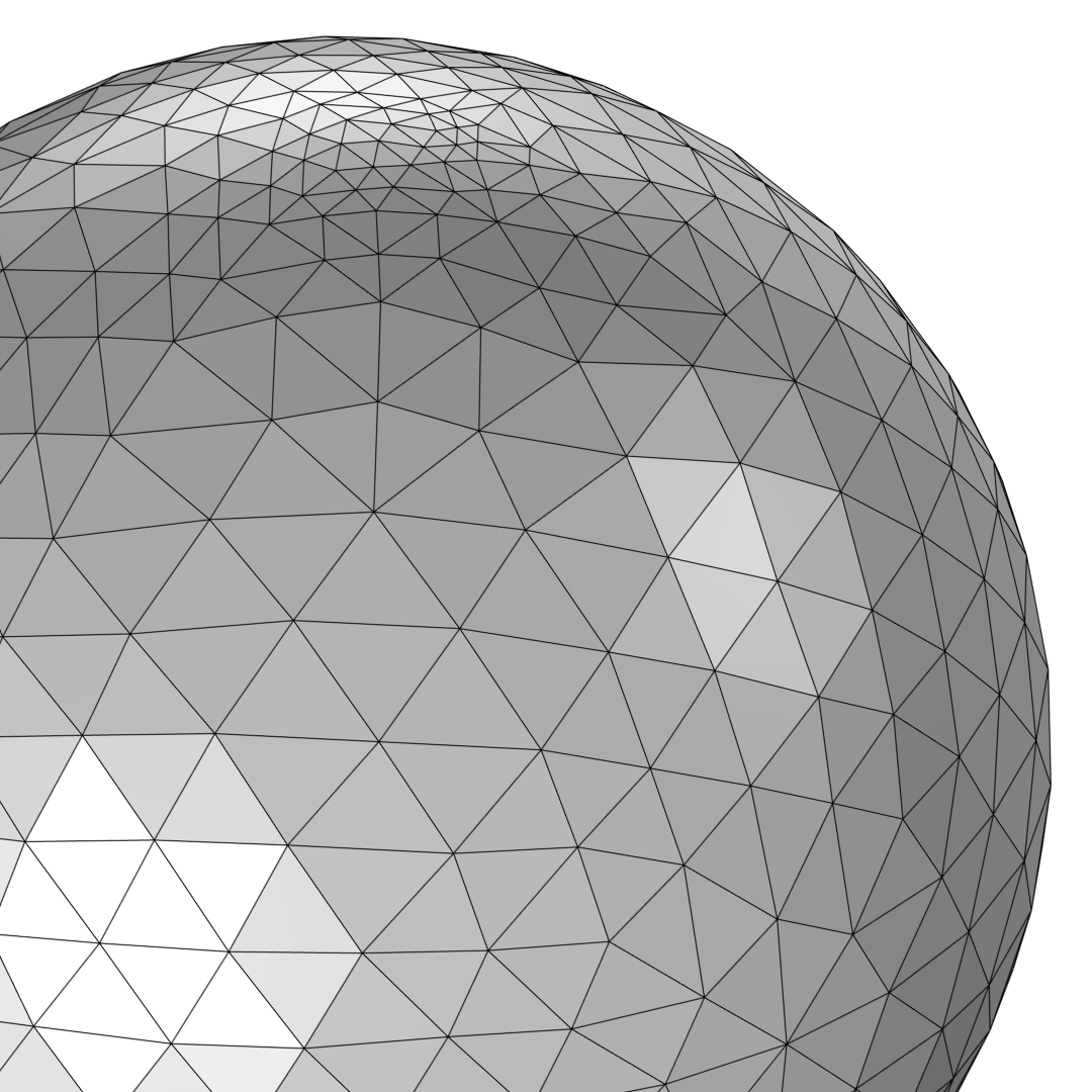
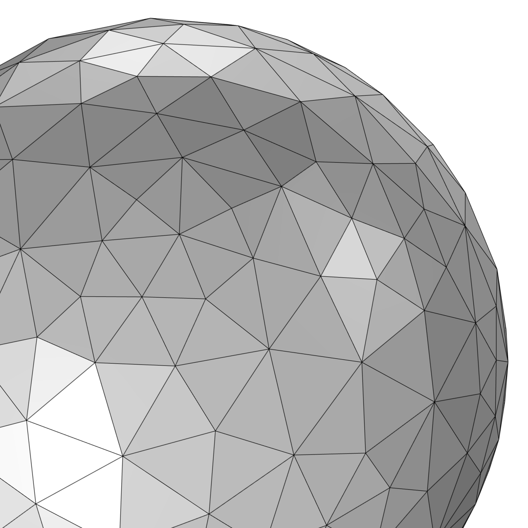
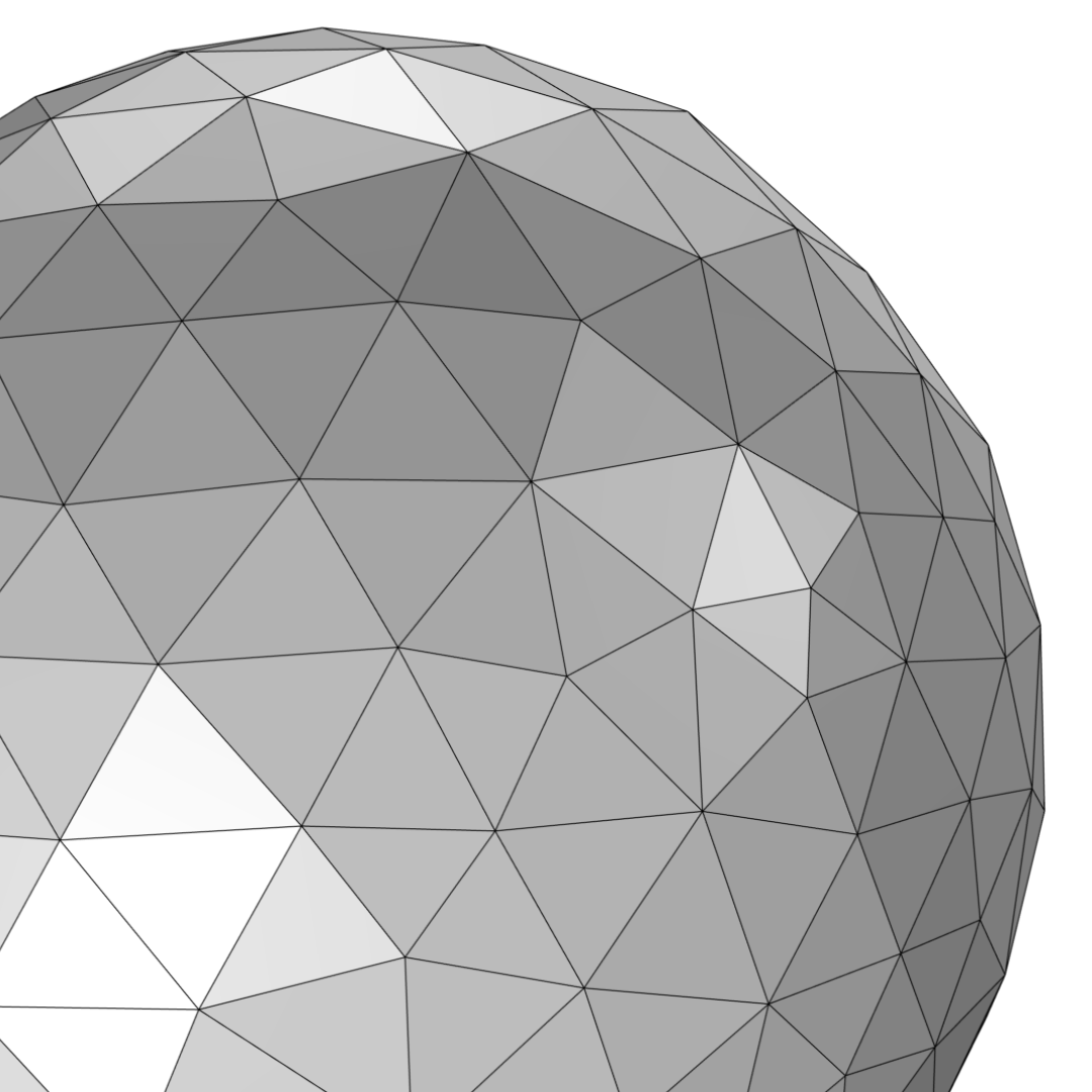
The coarse surface mesh of the sphere is refined once using Refine (left). The image in the middle shows the result after using the Adapt operation. In the image to the right, Free Triangular has been used to remesh the surface of the sphere.
As you can see in the images above, when using the Refine operation, all triangles are refined, even the smaller ones at the top. The Adapt operation coarsens the finer mesh at the top and refines the coarser mesh, resulting in elements of more similar size. You can also use Free Triangular to get elements of a more similar size.
Since the Free Triangular operation generates an underlying smooth geometric surface and the Adapt operation can modify the existing mesh to coarsen it, it’s sometimes possible to use these operations for smoothing over small irregularities in the mesh. Adding multiple of the same operation or any combination of these operations for the same boundary selection will smooth out the mesh even further, as there is no memory of what the mesh looked like before the current mesh, such as its previous irregularities.
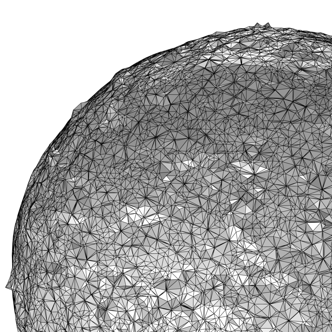
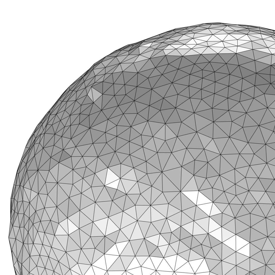
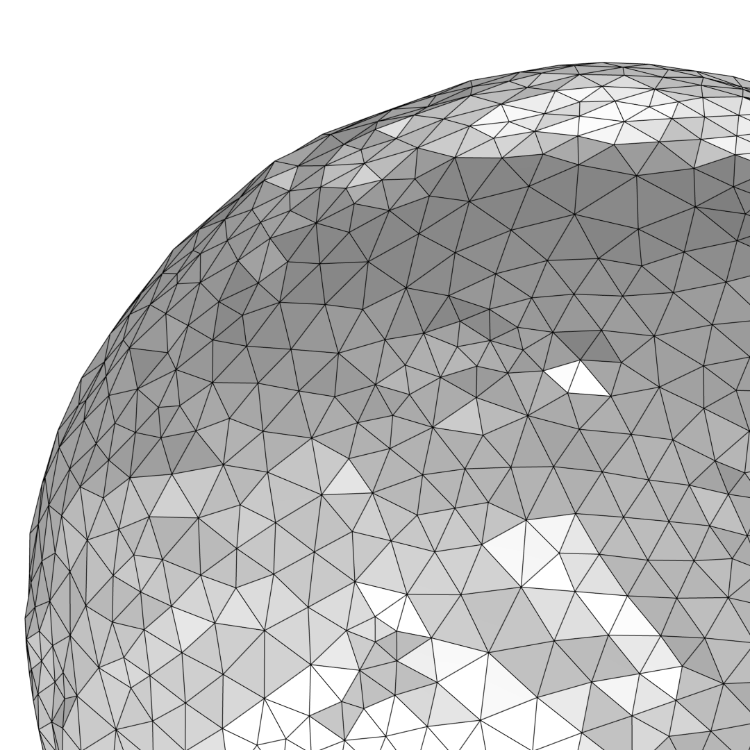
Smoothing over irregularities in an imported STL mesh (left) of poor quality. The image in the middle shows the result after running the Adapt operation twice. The mesh to the right shows the result after running the Free Triangular operation once.
Connecting Two Imported Meshes by Creating Edges and Faces in Empty Space
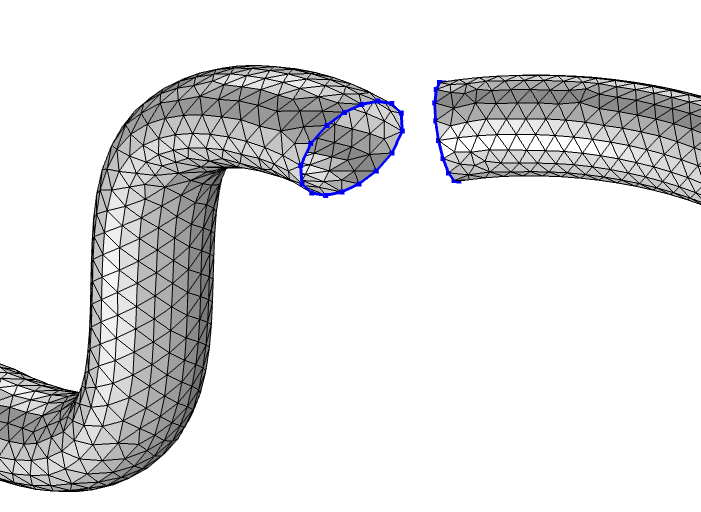
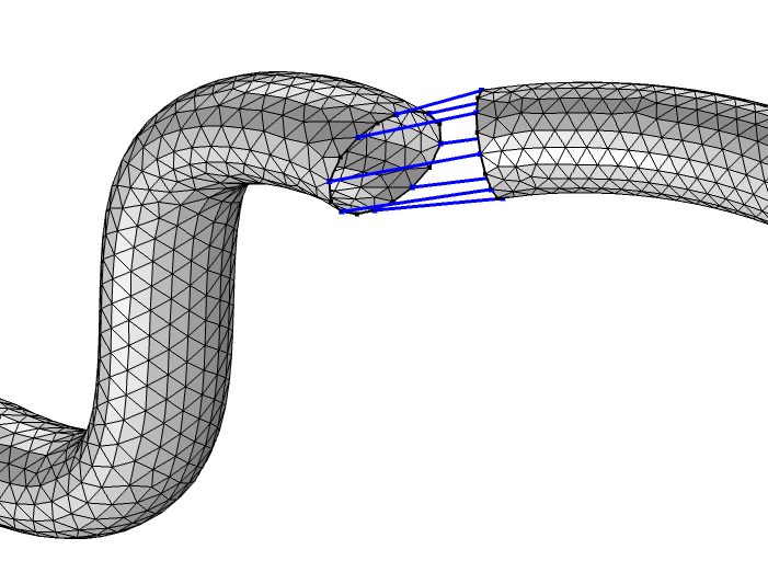
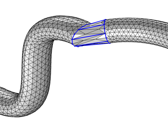
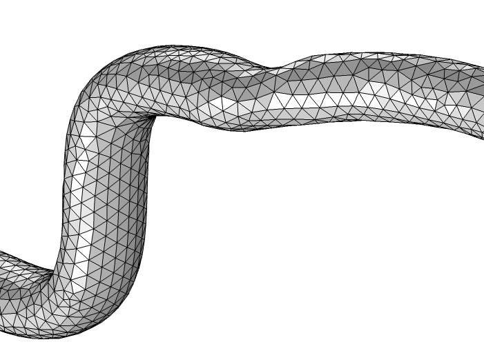
The Create Vertices, Create Edges, and Create Faces operations can be used for creating meshed entities in empty space. In the slide show below, we’ll see how these operations can be used for bridging a gap between two imported meshes that are disconnected. There are two imported, disconnected meshes of pipes, one with an oval cross section (S-shaped pipe to the left) and one with a circular cross section (the pipe to the right). The goal is to connect the edges highlighted in blue.
We start by using Create Vertices to make sure there are a similar amount of vertices on both meshes. Connect the vertices with meshed edges using Create Edges. Created edges are always straight, meshed edges. Surfaces are then created within each edge loop using the Create Faces operation. Lastly, the surfaces are joined and remeshed using Free Triangular. As you can see in the last image, remeshing the joined surface makes it smoother, and it’s now difficult to see that the two pipes were not connected to begin with.
The created surfaces will always be as planar as possible, so it might be necessary to add more mesh vertices and edges in order to resolve a curved surface. To smooth out the generated surfaces and get a good quality mesh with elements of similar size, the surfaces can be adapted or remeshed, as discussed in the previous section.
Intersecting vs. Partitioning a Surface Mesh
If you have two imported surface meshes that are intersecting, use Union to intersect the surfaces and update the domain information. It’s often useful to remesh or adapt the surfaces afterward to get a good quality surface mesh, as shown below.
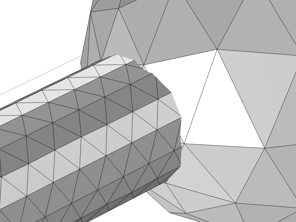
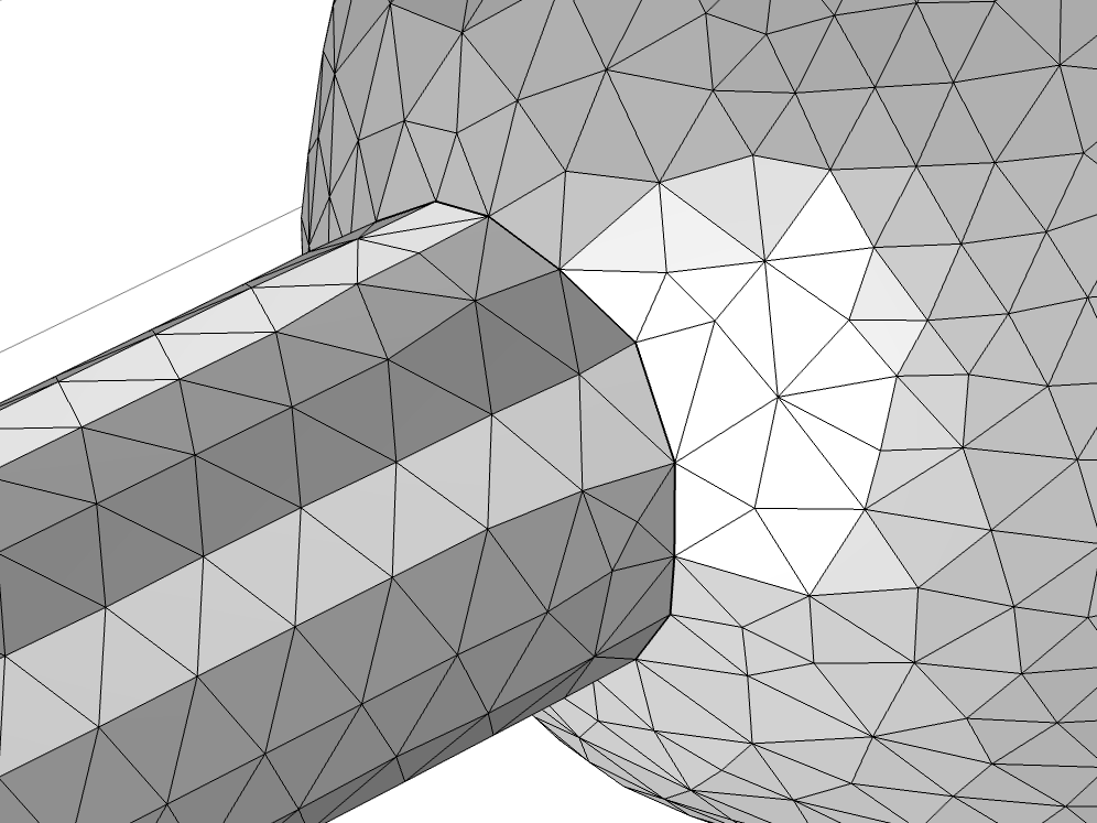
Uniting two imported surface meshes using the Union operation (left) and the resulting mesh after modifying it using Adapt (right).
Sometimes, it’s necessary to partition or intersect a mesh in order to obtain the desired boundaries for later assigning boundary conditions. Let’s take a look at an important distinction between the intersect operations and partition operations by intersecting and partitioning the following surface mesh at z = 1. As seen below in the image to the right, the plane crosses in the middle of the triangles. The intersect operation will divide the elements where the plane is located to add a straight geometrical edge. The partition operation will add the geometrical edge along the existing mesh edges that are closest to the plane.
The Intersect with Plane operation is supported for surface meshes only. It intersects the mesh elements, which means that the triangles are divided at the location of the plane and new mesh vertices, edges, and triangles are introduced where they are needed. As a result, the intersected surfaces are partitioned with a straight edge, as shown below in image to the left. If needed, you can use the Cleanup of resulting mesh algorithm to, for example, remove the short mesh edges and small elements that may have been introduced in the resulting mesh.
Note: To see another example of the Intersect with Plane operation and learn about it in more detail, check out the STL Import Tutorial Series.
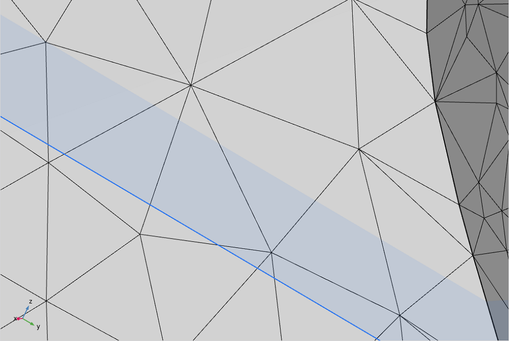
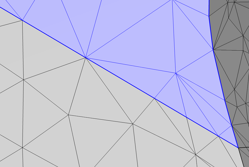
Images showing a mesh before and after the Intersect with plane operation has been built. Left: A surface mesh with a plane placed in z = 1, highlighted in blue. The plane intersects the surface mesh at the upper edge of the blue area. Right: The resulting upper boundary (highlighted in blue) has a straight lower edge.
The partition operations are supported for volume meshes and surface meshes. It’s possible to partition the domains or surfaces of a mesh using different shapes, including a:
- Ball
- Box
- Sphere
- User-defined expression
The word partition here means that new entities are formed based on whether an element is included within the shape or not. The mesh elements and mesh edges are not divided. This means that the number of mesh elements in the domains and on the surfaces stays the same and that the created edges will follow the existing mesh edges, as seen in the image to the right.
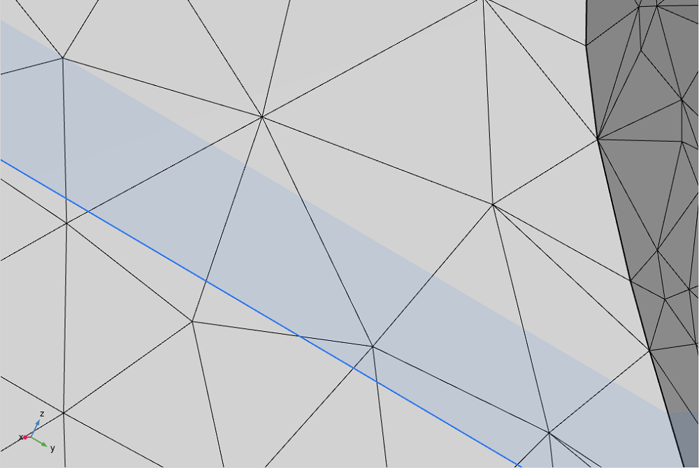
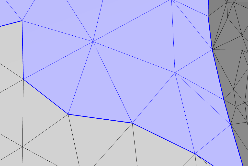
Images showing a mesh before and after the Partition with Box operation has been built. Left: A surface mesh showing a plane placed in z = 1, highlighted in blue, where the box will partition the mesh. Right: The geometrical edge follows the existing mesh edges as close to z = 1 as possible.
Partition Operations vs. Create Edges
While it’s possible to partition a surface using a partition operation, it’s also possible with the Create Edges operation. The partition operations are restricted to certain shapes or logical expression with their respective settings, but can quickly partition a mesh. On the other hand, the Create Edges operation is more flexible, as each mesh edge is selected manually. Due to this, this operation is typically used when isolating a smaller number of mesh elements.
Note: The Create Edges operation is featured within the STL Import Tutorial Series — download the application files to learn more.
For instance, we can use the Partition with ball operation to isolate the portion of a surface that is forming a spike in the mesh, as shown in the figures below. We can set the conditions for the partition to include triangle elements if some or all of the mesh vertices of the element are located within the sphere. Alternatively, we can use the Create Edges operation if we want more control over selecting which mesh edges to convert into edges that bound the new surface.
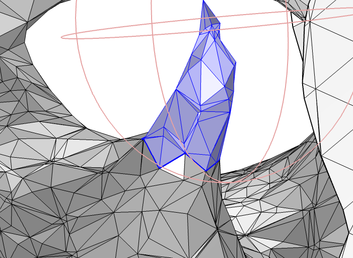
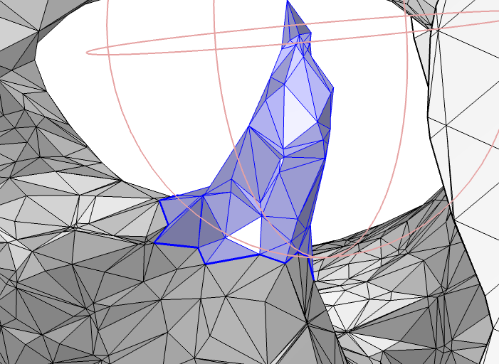
In the image to the left, the condition for the partition is set to include a mesh element if all its vertices are inside the ball, while the image to the right shows the same operation with the condition set to include a mesh element if only some of its vertices are inside the ball. In both cases, the edge of the new surface (highlighted in blue) becomes jagged.
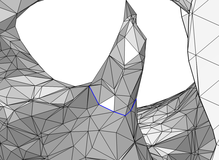
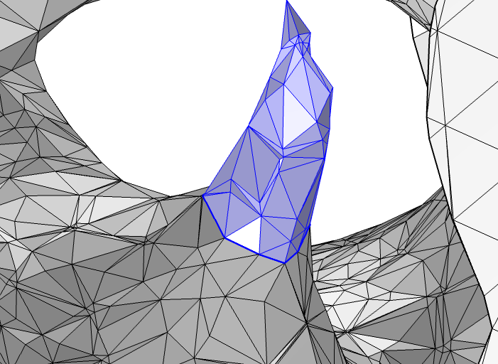
In this example, we right-click with the mouse to select each mesh edge in the Graphics window (left), which is a rather quick process. This results in a more even shape of the bottom edge of the selected surface (right, highlighted in blue).
Automating Commonly Used Operations
When you are editing and repairing imported meshes, you might use some operations more than others or realize that a particular sequence of operations is used every time you set up a new simulation. One way of automating your modeling workflow, or parts of it, is by setting up a model method or an add-in.
For example, when working with imported meshes representing porous structures, there are often narrow “bridges” connecting one part of the mesh to another. These bridges can be problematic when creating a geometry or when remeshing the surfaces, as the surface of the bridge easily becomes self-intersecting. Therefore, it’s sometimes necessary to remove them from the mesh. A quick way of doing so is to first set a rotation center at a boundary, which you can do by middle-clicking with the mouse. Next, use the Ball Partition add-in, which creates a Partition with ball operation at the rotation center (shown below on the left). This will isolate a portion of the surface as a separate boundary.
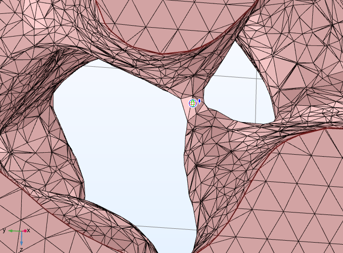
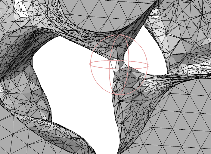
A surface mesh of a porous structure. The pillar-like part in the middle of the image creates a narrow bridge from one part of the surface to another. Here, we have set the rotation center on the bridge (left image) and used the Ball Partition add-in to position a Partition with Ball operation based on the position of the rotation center (right).
This add-in makes it easy to remove the narrow bridge and repair the holes.
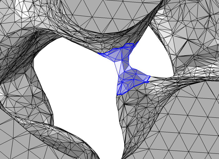
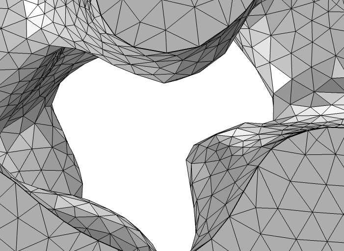
The bridge is isolated as a separate boundary and selected (left, highlighted in blue) to be deleted. The image on the right shows the adapted mesh after the holes have been filled and the mesh has been adapted.
Volume Meshes
If you want to remesh an imported volume mesh, you can clear the Import domain elements check box in the settings for the Import operation. Another option is to delete the domain elements while keeping the surface mesh and the unmeshed domains. To do this, use the Delete Entities operation, select the domains for which to delete the elements, and select the Keep as unmeshed domains check box.
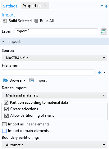
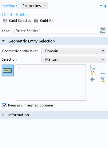
To restore the tetrahedral mesh in the domains, use the Free Tetrahedral operation.
Concluding Thoughts
There are numerous ways to edit imported meshes, and COMSOL® offers multiple features that make these variations possible.
If you haven’t already, check out the two-part tutorial series available in the Application Libraries. In the first part of the series, a geometry object is created based on the STL mesh and is later intersected with a block. In the second part, two surface meshes are imported and filled with a tetrahedral mesh directly, without creating a geometry based on the STL mesh. Together, these tutorials give insight into repairing and editing any type of imported surface mesh.
Learn More
Check out these resources to learn more about meshes:
- How to Use Topology Optimization Results as Model Geometries, a blog post where we discuss how you can create meshes from simulation results using the Filter or Partition datasets in COMSOL Multiphysics. We also go over how this procedure can be used to set up verification studies of topology optimization results.
- How to Refine and Adapt Imported Meshes, a blog post where we provide an overview of using the Refine and Adapt operations and the General modification setting when modifying mesh.
- Analyzing Porous Structures on the Microscopic Scale, a tutorial model that showcases the remeshing of an STL file.
- Head and Torso HRTF Computation, a tutorial model that showcases the partitioning of an STL mesh.




Comments (0)