
Electromagnetic scattering simulation for an object with continuous rotational symmetry can be performed in 2D axisymmetric models instead of 3D to drastically reduce computational time and resources. In this blog post, we discuss how to simulate arbitrary plane wave incidence in 2D axisymmetric models by making use of plane wave expansion in cylindrical coordinates.
Scattered Field Formulation in Electromagnetic Simulations
When a propagating electromagnetic wave hits an object, the interaction with the object will typically change the propagation properties of the original wave. This type of scattering event is often of great interest in RF, microwave, and optical engineering. To facilitate accurate simulation of electromagnetic scattering, the RF Module and Wave Optics Module, add-ons to the COMSOL Multiphysics® software, provide a convenient Scattered Field formulation, where the total field is written as the sum of the user-defined background field and the scattered field that will be solved for by the simulation. Common options for the background field include a plane wave and Gaussian beam. You also have the flexibility to define an arbitrary background field.
Plane Wave Expansion in Cylindrical Coordinates
Among different background fields, plane wave is the most commonly used. However, unlike in 2D and 3D models, we cannot simply set the background field in a 2D axisymmetric model as a plane wave propagating in an arbitrary direction since it breaks the rotational symmetry. Fortunately, with the tricks that we are going to demonstrate here, we can achieve a plane wave background field in a 2D axisymmetric model.
Now let’s consider a general plane wave background field given by
Without loss of generality, \bm{k} is assumed to be in the xz-plane and the angle between \bm{k} and the z-axis is given by \theta. For the sake of simplicity, we only consider p-polarized incidence, but s-polarization can be implemented in a similar fashion. For p-polarization, \bm{E_0}=E_0 (cos \theta \bm{\hat{x}} + sin \theta \bm{\hat{z}}) and \bm{k} = k (sin\theta \bm{\hat{x}} – cos\theta \bm{\hat{z}}), where k=\omega/c. Thus, the plane wave can be written as
where \phi=atan\frac{y}{x} is the azimuthal angle and r=\sqrt{x^2+y^2}. Here, the factor e^{i\omega t} is omitted for simplicity but implied. Two crucial ingredients are needed to achieve the expansion: plane wave, partial wave expansion in cylindrical coordinates
and coordinate transformation from Cartesian to cylindrical
where J_m is the Bessel function of the first kind of order, m. Combining the previous equations and some algebra leads to
Now, we can finally write the plane wave background field as an infinite sum of azimuthal modes with mode number m in cylindrical coordinates, meaning that it can be implemented into a 2D axisymmetric simulation. Furthermore, positive m and negative m only differ by a phase factor, so, in principle, the summation only needs to be carried out from m=0 to m=N. For example, the \bm{r} component of the background field can be written as
where \chi is a step function such that \chi(m)=1 for m=0 and \chi(m)=2 for m>0. Although the summation is extended to infinity, if the size of the scatter is comparable to the wavelength, the result will converge after only a few terms.
Investigating the Scattering of a Prolate Spheroid
As a concrete example, we will use COMSOL Multiphysics to study the scattering of a silver prolate spheroid in the infrared frequency range from 5 THz to 50 THz. First, we create a prolate spheroid with semiaxis a=2\ \mu m and b=5\ \mu m. The optical property of silver in the relevant frequency range can be found from the material library. The Impedance Boundary Condition can be applied to the surface of the spheroid since the conductivity of silver is high in this frequency range while we still want to account for small losses. Perfectly matched layers (PMLs) are added on the outer boundaries to absorb the outgoing radiation.
Next, we define each component of the background field as derived previously at a fixed azimuthal mode number, m, and use them as the background electric field in the scattering formulation. In the Variables subnode, we also defined the scattering cross section, which is the surface integral of the Poynting vector. (We will talk more about this later.)

Each component of the background field is defined as a variable.
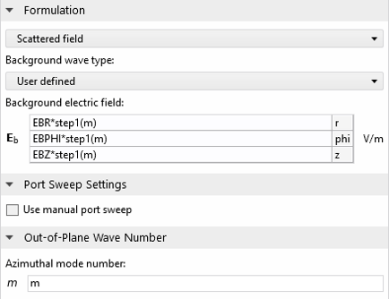
A scattered field formulation is used. The step function takes into account the positive and negative m.
Lastly, we set up the frequency sweep to sweep the frequency range from 5 THz to 50 THz at 0.25 THz increment and use the auxiliary sweep to sweep m from 0 to N. Using frequency and auxiliary sweeps instead of the more common parameter sweep improves the simulation speed.
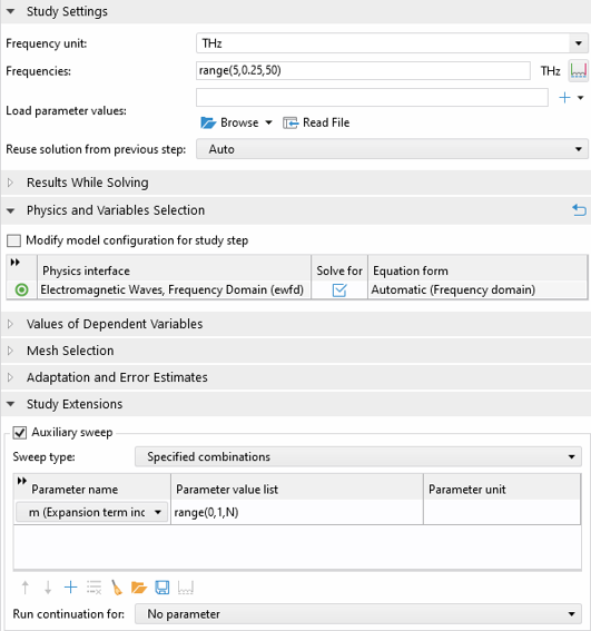
The settings for the frequency sweep and auxiliary sweep.
Even with extremely fine setting for the element size, the broadband simulation finishes in only about 5 minutes. In the postprocessing, we will use some tricks to visualize both the total scattered field as well as the total background field to make sure it closely resembles a plane wave. To do so, we make use of a Mirror 2D dataset (see the associated model for details). This way, we can plot the field distributions at \phi and \pi-\phi in the same plot. The total scattered field is the sum of the scattered fields for each expansion term. For example, the norm of the total scattered field at 30 THz and \phi=0 can be calculated as
sqrt(abs(sum(withsol('sol1', ewfd.relEz*cos(m*0), setind(m,index),setval(freq,30[THz])), index, 1, N+1))^2 + abs(sum(withsol('sol1', ewfd.relEr*cos(m*0), setind(m,index),setval(freq,30[THz])), index, 1, N+1))^2 + abs(sum(withsol('sol1', j*ewfd.relEphi*sin(m*0), setind(m,index),setval(freq,30[THz])), index, 1, N+1))^2)
Here, the withsol operator is used to pick out the scattered field at frequency 30 THz and azimuthal mode number index. The sum operator is used to sum over the contribution of each solution.
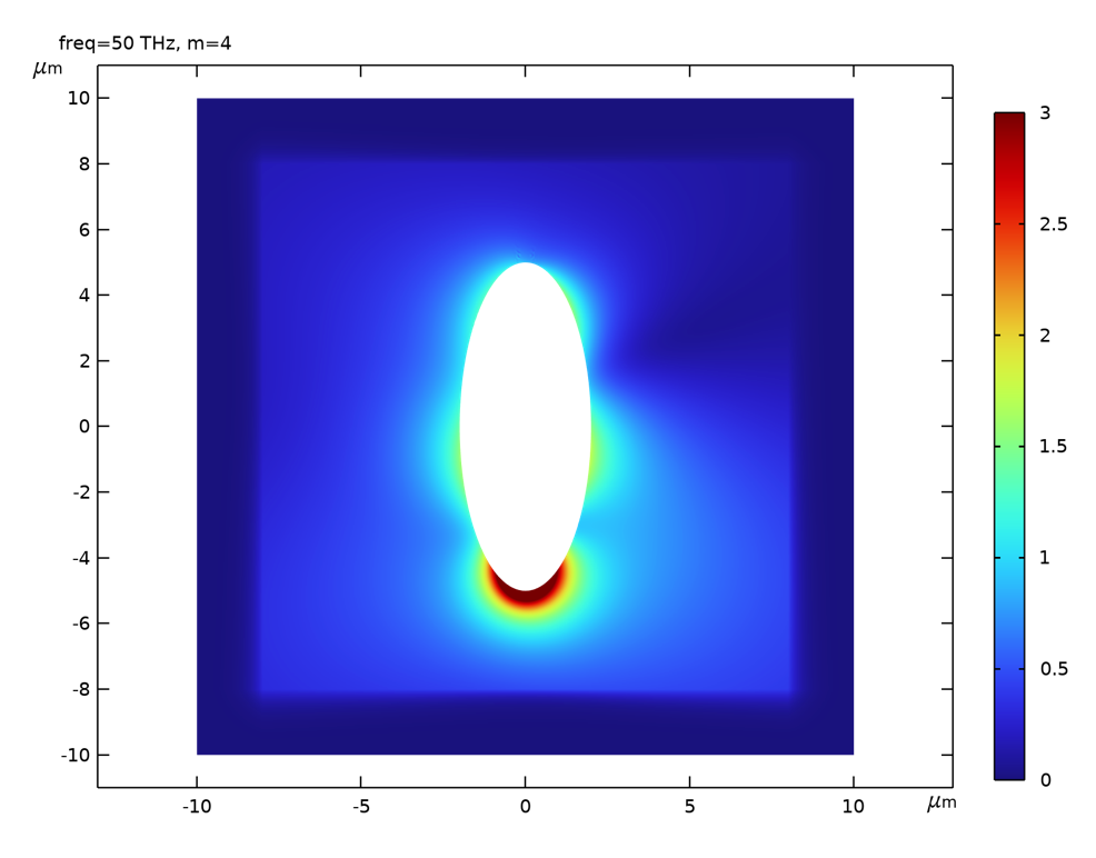
A 2D plot of the norm of the total scattered field at 30 THz by summing over the contributions from each expansion term.
Alternatively, we can make use of the Revolution 2D dataset to plot the scattered field in 3D. Note that by default, the Revolution 2D dataset simply implements a body of revaluation, where the azimuthal angle dependence is ignored. The correct \phi dependence can be manually added by first enabling the Define variables under the Advanced tab in the settings of the Revolution 2D dataset. This enables a variable called rev1phi for the azimuthal angle. Then the correct expression for the norm of the total scattered field in 3D is:
sqrt(abs(sum(withsol('sol1', ewfd.relEz*cos(m*rev1phi), setind(m,index),setval(freq,30[THz])), index, 1, N+1))^2 + abs(sum(withsol('sol1', ewfd.relEr*cos(m*rev1phi), setind(m,index),setval(freq,30[THz])), index, 1, N+1))^2 + abs(sum(withsol('sol1', j*ewfd.relEphi*sin(m*rev1phi), setind(m,index),setval(freq,30[THz])), index, 1, N+1))^2)
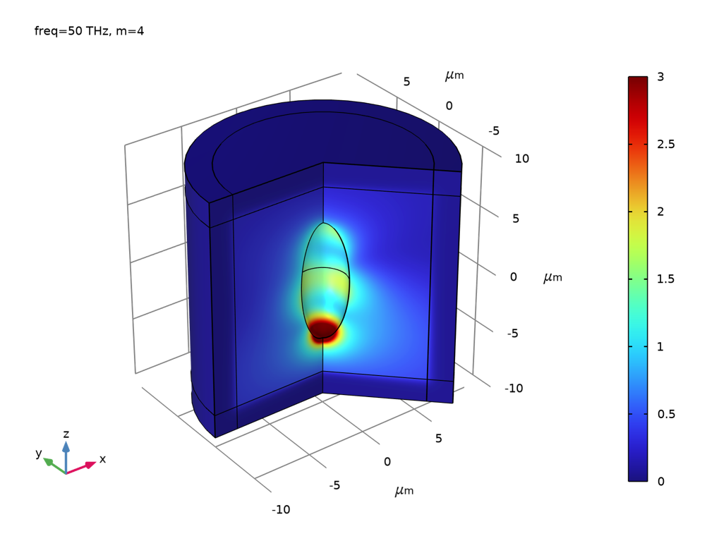
A 3D surface plot of the same field using the Revolution 2D dataset.
The background field can be plotted in a same fashion as the scattered field. We can see that with only N=4 in the expansion, the background field around the scattered is indistinguishable from a plane wave.
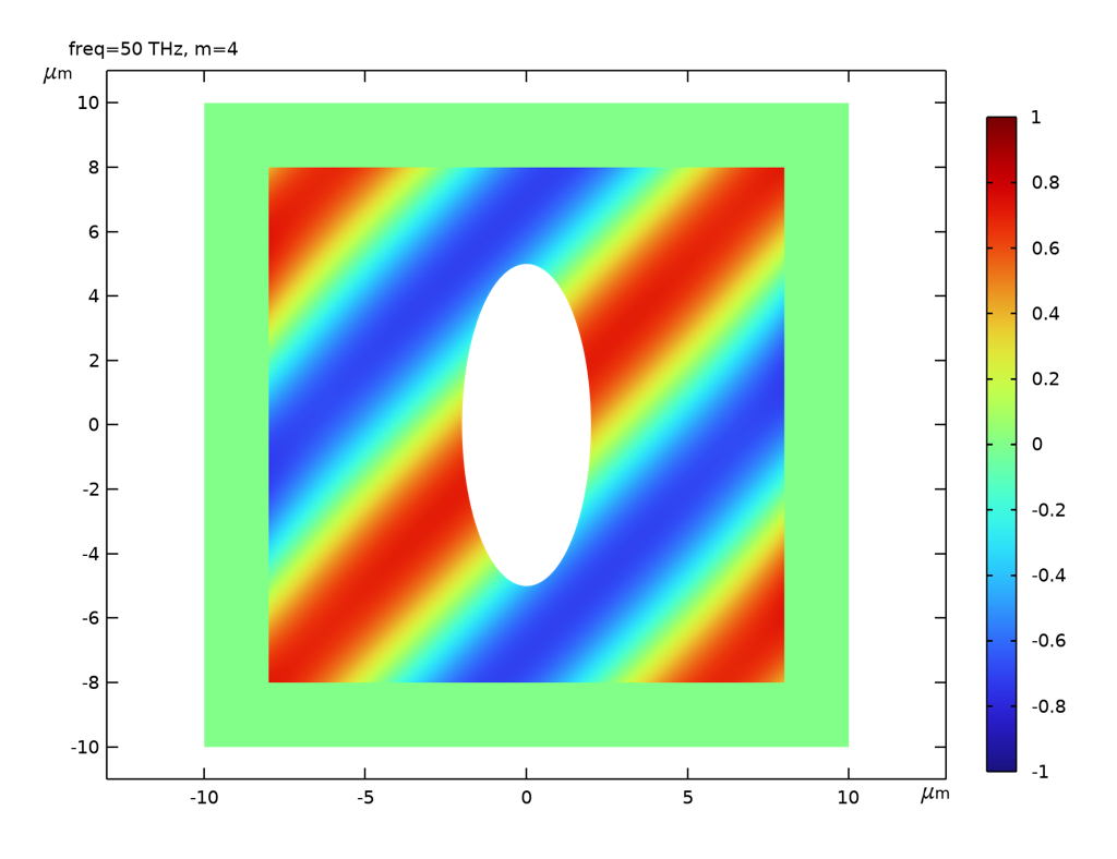
The z-component of the total background field by summing over the contributions from each expansion term.
Lastly, we would like to plot the scattering cross section as a function of frequency. Note that in Variables we defined the expression of the scattering cross section. The total scattering cross section can be calculated as
-withsol('sol1', sigma_sc, setval(m,0),setval(freq, freq))-sum(withsol('sol1', 0.5*sigma_sc, setval(m,val),setval(freq, freq)),val,1,N)
The minus sign is due to the fact that the surface normal on the spheroid surface is pointing to the interior. The multiplicative factor of 0.5 for terms with m>0 is to compensate the doubling of energy since each term is the sum of positive and negative m. Usually, the total scattering cross section is not simply the sum of that calculated for each expansion term. This is because the scattering cross section and the Poynting vector are directly associated with energy, not the field. The energy is proportional to the square of the field. Thus, when you square a sum of many terms, cross terms emerge in addition to the sum of the squares. Luckily, in our case, the cross terms all vanish because of the orthogonality of the azimuthal modes, i.e., when integrating over \phi, the cross terms are all zero. Consequently, the total scattering cross section is just the sum of that from each expansion term. As we can see, the scattering cross section of the prolate spheroid is qualitatively similar to that of a sphere, which is the well-known result from Mie’s calculation.
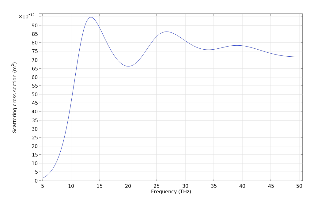
Scattering cross section for the silver prolate spheroid in the infrared frequency.
Conclusion
In this blog post, we introduced a method for simulating the scattering properties of a body of revolution under plane wave excitation using a 2D axisymmetric model. There are tremendous rewards for performing the simulation this way compared to the full 3D simulation. The costs of computational memory and time are at least one order of magnitude smaller. Therefore, fine mesh can be used to achieve very high simulation accuracy. In addition, since the RAM requirement is small while a number of parameters need to be swept, using the Batch Sweep feature to simultaneously run multiple simulations at the same time could offer significant advantage, although we did not explicitly demonstrate it here. In our example model, we demonstrated the calculation for the scattered field and the scattering cross section, but other quantities of interest associated with a scattering problem, such as the far-field radiation pattern, can be derived as well. Lastly, we need to note that cautions must be exercised to keep track of the phase factor associated with the mode number when calculating various physical quantities.
Try It Yourself
Try the Plane Wave Expansion model yourself by clicking the button below, which will take you to the Application Gallery entry:


Comments (0)