When undergoing testing for electromagnetic compatibility compliance, many products rely on biconical antennas. In order to help with this testing, it is important that these antennas possess broadband characteristics. We explore how simulation can help you ensure this.
An Introduction to Biconical Antennas
A biconical antenna is a broad-bandwidth antenna that is comprised of two conductive objects, which are cone-shaped. These broadband dipole antennas typically feature a bandwidth of three or more octaves. What allows the antenna to achieve such an extremely wide bandwidth? It can be attributed to its structure. In particular, the antenna’s two symmetrical radiating cones.
Biconical antennas are noted for their use in conducting electromagnetic compatibility (EMC) testing. This testing ensures that products adhere to the electromagnetic compatibility compliance guidelines that are issued by governing organizations. It is very important for these antennas to include the broadband characteristics needed to meet such guidelines.
To ensure that the antenna’s design meets these requirements, we can turn our attention to the power of simulation.
Modeling the Power Source
The Biconical Antenna model in our Model Gallery features two conical, metallic, radiating elements, with a dielectric-filled coaxial feed structure at its center. This structure houses a small cylindrical domain that contains the antenna’s power source, which is not included within the modeling domain.
As an alternative, this source can be modeled by implementing a coaxial lumped port boundary condition at the boundary that is facing the coaxial cable. This results in a wave that is launched down the coax. A perfectly matched layer is used to truncate the area of free space surrounding the antenna.
![]()
The biconical antenna model.
Wires, which are modeled as perfect electric conductors, are used to connect the inner and outer conductors of the coax to the conical radiators. Within each cone, there is a small symmetric cutout that allows for ample clearance for mounting and assembly purposes. The distance between the radiators and the surface area of the cone’s end tips are responsible for the reactance of the antenna’s input port. Modifying this distance can thus change the performance of the antenna.
The Antenna’s Bandwidth and Radiation Pattern
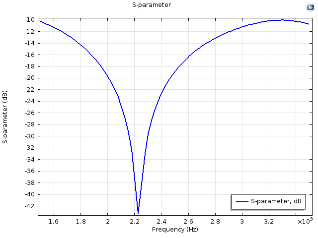
The first graph highlights the frequency response of the biconical antenna. The results show that the bandwidth is significantly wider than that of a traditional dipole antenna, as S11 is less than -10 dB from 1.5 GHz to 3.5 GHz. This introductory example model simulates only a bandwidth of one octave.

Frequency response.
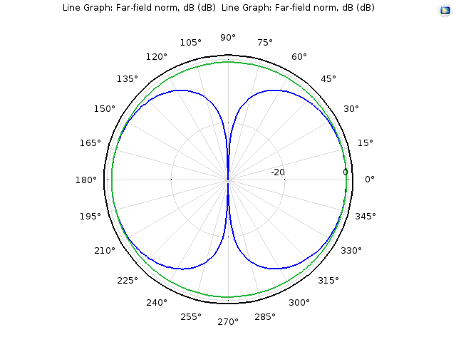
We can then shift our focus to the antenna’s radiation pattern. The simulation results show the far-field radiation pattern at 1.9 GHz at the E-plane (shown in blue) and the H-plane (shown in green). The resulting pattern resembles the radiation pattern of a dipole antenna.

Far-field radiation pattern.
Concluding Thoughts
The model discussed here illustrates that biconical antennas are well suited for applications requiring an omnidirectional radiation pattern as well as a wide bandwidth. In the next release of COMSOL Multiphysics — version 5.1 — we will include a new commercial look of this model, similar to that featured in the picture below. Stay tuned!
![]()
A biconical microwave antenna. (“Small Biconical Microwave Antenna (SBA 9113: 0.5 – 3 GHz, SBA 9112: 1 – 18 GHz)” by Schwarzbeck Mess-Elektronik — Own work. Licensed under Creative Commons Attribution Share-Alike 3.0, via Wikimedia Commons).


Comments (0)