
Bearings are one of the oldest inventions in the world, and one of the most common. Often, these parts are found in rotating machinery, helping to support other components, reduce friction between elements, and transfer various loads. To work properly, bearings must be aligned correctly, or else they create vibrations that can lead to premature device failure. Using the COMSOL® software, you can study how bearing misalignment affects vibration in a rotating machine.
Bearings: An Age-Old Part for Modern-Day Rotating Devices
Humans have used bearings for a long, long time, possibly even before the wheel was invented. Ancient Egyptian hieroglyphs have depicted stone versions of these parts (which were used for devices like hand drills), but the earliest bearings to be discovered came later, found on the Roman Nemi ships (which crashed around 40 BC). Leonardo da Vinci also sketched a bearing for his helicopter design, and Galileo described the first caged ball bearing.

Depiction of a rolling element bearing supporting a rotor shaft that is off center.
Today, there are many different types of bearings, ranging in shape and size depending on the use. For instance, giant roller bearings can move buildings (such as lighthouses), while tiny ball bearings are helpful for MEMS. Another example is the hydrodynamic bearing, which includes a thin fluid film that helps reduce friction between parts and is useful for rotary machinery in:
- Steam turbines
- Cooling pumps
- Ships
- Fine machining and finishing
- Electric motors
A common issue for rotating systems is bearing misalignment, which affects their overall performance. For instance, a misaligned bearing is one of the main causes of vibrations, leading to excess noise and (eventually) the premature failure of the device. In addition, misaligned bearings can increase the torque for a rotating machine, which makes it consume more power during operation.
Despite these drawbacks, bearing alignment or realignment isn’t always performed when setting up or maintaining a device, as it’s not clear how beneficial the payoff is. (For example, is it worth realigning all 100+ bearings in a car for only a small increase in efficiency and lifetime?) Besides, all bearings can handle a certain amount of misalignment, although this depends on the type and function of the part.
To gain insight into how misaligned bearings affect various machinery, engineers can use simulation. Here, we examine the effect of bearing misalignment on a rotating system using the Rotordynamics Module, an add-on to the Structural Mechanics Module and the COMSOL Multiphysics® software.
Analyzing Bearing Misalignment in COMSOL Multiphysics®
For this example, the model is relatively simple, consisting of two hydrodynamic bearings, a disk in between them, and a rotor shaft supported on them. The disk is placed between the bearings, and its eccentric mounting on the rotor (or the offset of the center of gravity from the geometric center of the disk) results in a mass imbalance that causes the latter to whirl. To test the effect of the bearings in this setup, a time-dependent simulation is performed twice, once with both bearings aligned correctly and once with the right bearing misaligned.
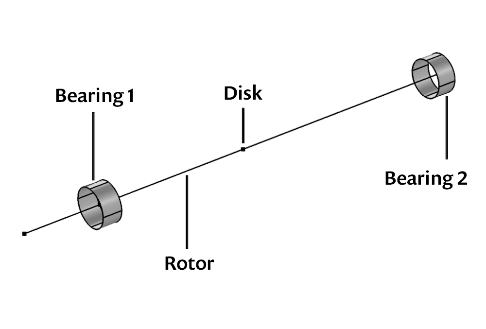
Setup for the rotor and bearing simulation.
The Beam Rotor with Hydrodynamic Bearing interface enables you to capture the behavior of this assembly, easily coupling the behavior of the rotor and bearings. Also included in the simulation is the material and geometric properties of the rotor as well as important parameters for the fluid film on the bearings, such as the dynamic viscosity, compressibility, and more. (For additional details, you can view the bearing misalignment tutorial documentation.)
How Does Bearing Alignment Affect Vibration in a Rotating System?
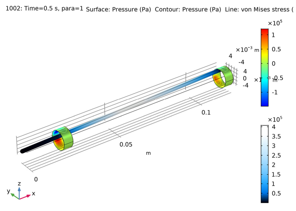
To answer this question, let’s first take a look at the stress in the rotor and pressure on the bearings. Here, the maximum amount of bending stress is directly in the middle of the rotor, and there’s pressure on both bearings. Paired together, these results indicate that the shaft will bend in such a way that it forcefully presses against the fluid film, in turn putting pressure on the bearings. When the rotor brushes against the thin film and bearings, it could lead to vibrations. But is the pressure worse when the bearing is misaligned?
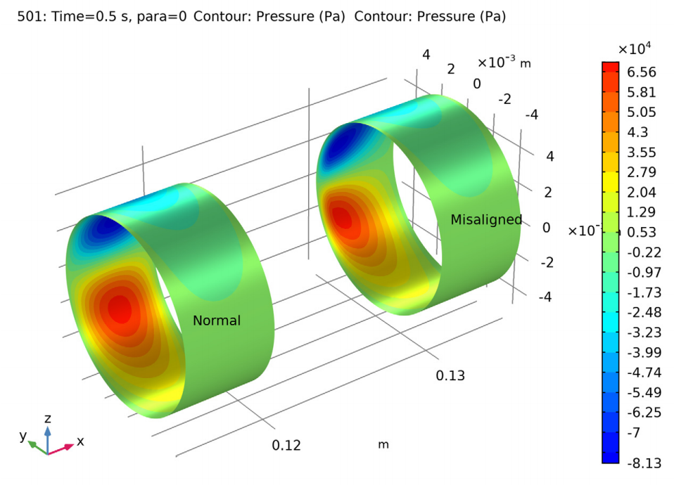
From the results, it looks like while the maximum pressure is about the same, the distribution is off-center in the misaligned bearing, since the pressure distribution in the bearing supports the load of the shaft. The pressure distribution in the bearings is directly affected by the thickness of the fluid film, so being off-center indicates that contact could occur near the edge of the bearing.
The von Mises stress in the rotor and pressure on the bearings (left) as well as a comparison of the pressure distribution when the right bearing is and is not aligned (right).
You can also determine how quickly the rotor stabilizes in each case. Here, the rotor with a misaligned bearing has a higher initial velocity. Thus, the rotor tries to reach stable equilibrium faster, which causes it to stabilize more quickly than the rotor with two aligned bearings. The larger amplitude in the oscillation of the velocity, though, means that the vibrations will be more severe with the misaligned bearing.
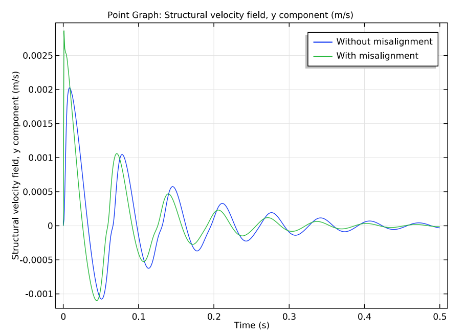
Velocity of the right bearing with and without misalignment.
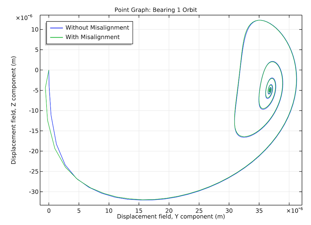
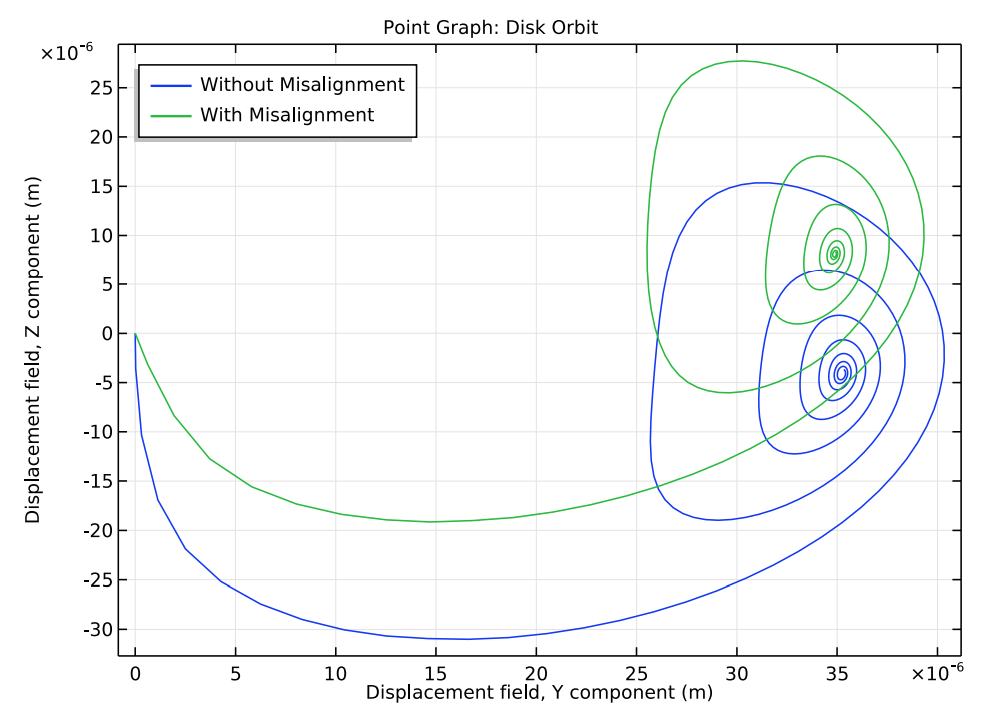
Next up, let’s examine the orbits of the rotor in both bearings, and how they compare when the right bearing is not aligned. As seen below, the orbit of the rotor in the left bearing is almost entirely unaffected by the misalignment. However, it plays a more important role in the orbit of the rotor in the right bearing. The whirl patterns remain similar, but the steady-state position of the rotor is higher in the misaligned bearing. Thus, the rotor with a misaligned bearing will rest close to (or against) the fluid film near the top of the bearing. Since the rotor will be off-center, its rotation during operation will likely cause the rotor to brush against the fluid film and bearing, increasing vibrations and causing both parts to wear out quicker.
Orbits of the left bearing (left), right bearing (middle), and rotor (right) when the right bearing is and is not aligned.
Another way to examine these results is with an animation, like those shown below. The magnitude of the rotor transverse motion in the bearing is very small. Therefore, the displacement of the rotor is scaled for better visualization. Here, you can see that the initial movement for the rotor is more extreme with the misaligned bearing, and it has a higher equilibrium position closer to the bearing.
Animation of the rotor without misalignment.
Animation of the rotor with a misaligned bearing.
With models such as this one, engineers can determine how much bearing misalignment impacts vibration in a rotating system. Through this type of analysis, they can visualize the effect of misalignment, determining whether it is worth the cost of aligning a certain bearing as well as how it may affect the lifetime of the rotor system.
Next Steps
Try modeling this example: Click the button below to head to the Application Gallery, which includes documentation you can view and an MPH file that you can download.
Further Reading
Learn more about simulating bearings on the blog:





Comments (1)
ZHEN LI
June 10, 2019Dear Bridget Paulus,
Thank your excellent works and learn much from your blog.
However, the first part of this technical paper tells history and theories of rolling bearings, while, the example is about journal bearings. What’s the application of this example case? And in this model .mph file, where is the initial rotating speed in the physics settings?
Thank you for your time.
Best wishes
Li