In our previous post on Meshing Considerations for Linear Static Problems, we found that, in the limit of mesh refinement, the solution to the finite element model would converge toward the true solution. We also saw that adaptive mesh refinement could be used to generate a mesh that would have smaller elements in regions where the error was higher, rather than simply using smaller elements everywhere in the model. In this post, we will examine a couple of common pitfalls of finite element modeling that arise when there is a singularity in the model.
An Example from Structural Mechanics
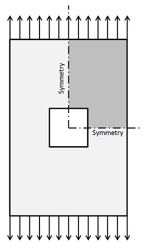
Let’s look at the problem of a flat plate under uniaxial tension with a square hole cut in it. This is similar to the example from earlier in that we can exploit symmetry and only model one quarter of the structure.

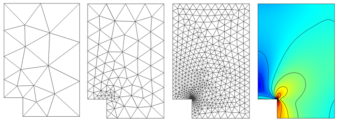
As before, we can use adaptive mesh refinement to let COMSOL insert more elements into regions where the error is estimated to be large:

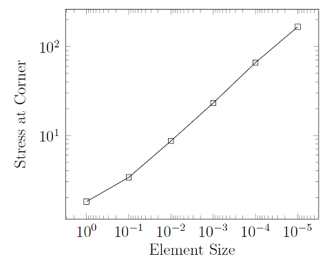
We observe that smaller and smaller elements are being inserted at the inside corner of the sharp hole. Let’s also plot out the stresses at this inside corner as a function of the mesh size:

From this plot, it appears that the stresses are getting larger and larger, no matter how fine we make the mesh. In fact, that is exactly what is occurring here; the stresses at the sharp corner are non-convergent with respect to mesh refinement because we have a singularity in the model. This is actually completely accurate — stresses in sharp corners are theoretically infinite. Whenever you see this kind of non-convergent behavior, it is likely that you are looking at the manifestation of a singularity in your model.
In structural engineering practice, sharp inside corners are something to avoid. You would be justified in saying that one way of preventing this problem is to round off the sharp corners of the model where these singularities appear. Doing so would lead to a model that predicts stresses that converge with mesh refinement, but it would still need to have a lot of elements in this inside corner. So let’s introduce other approaches to dealing with these singularities.
Evaluating a Model Globally
One approach to dealing with these singularities is to just ignore them. An important feature to understand about the finite element method is that it allows local inaccuracies, since it is formulated in a way that minimizes the global error in the model. The stresses we are predicting in the above model are incorrect, but if you evaluate the stresses at a distance of around 2-3 mesh elements away from the singularity, the stress solution there does converge. Thereby, if we’re interested in the stresses away from the singularity, the mere presence of the singularity does not pollute the predictions elsewhere.
Taking the Derivative of the Solution Field
It is also important to realize that the singularities manifest when you are taking the derivative of the solution field. In structural mechanics, we solve for the displacement field, \bf{u}, and compute the stresses from the strains, \bf{\sigma =C : \epsilon}, where strain is defined in terms of the gradient of the displacement field: \epsilon = 1/2 \bf{ [ (\nabla u)^T + \nabla u] }. When you think of the stress as being the gradient of the displacement field, it also becomes a little bit clearer why the solution for the stresses goes to infinity at a sharp corner. However, if you are only interested in the solution field, \bf{u}, this is not singular, even at the sharp corner, and does converge with mesh refinement.
Evaluating the Integral around the Singularity
There is one more common case when a singularity is acceptable: if you are only interested in an integral quantity as output of your model. For instance, the total elastic strain energy of a system composed of a linear material is:
If we evaluate this for a domain that includes a singularity, such as the plate with the square hole, this integral will converge rapidly with mesh refinement, even though the integrands are non-convergent at point(s) inside the domain. So if the only quantity that you want to get out is a function of an integral over a domain (or boundary) within your model, then your model can include singularities. The quantity that you are integrating will converge to the same value if you use a sharp or a round corner. This situation arises especially often in electromagnetics, where device inductance and capacitance are both evaluated as integrals of electric and magnetic fields over the domains.
Concluding Thoughts on Meshing and Model Singularities
To summarize, there are three common situations when it is acceptable to have a singularity in the model:
- When you are not evaluating the solution at the singularity, but some distance away
- When you are not evaluating the derivative of the solution at the singularity
- When you are evaluating the integral of some quantity, including the derivative of the solution, over a domain or boundary around the singularity
In these cases, you will observe convergence of your solution with mesh refinement. That said, you should still be careful when you observe non-convergent behavior anywhere in your model, and make sure that it is not skewing your interpretation of the results.
Finally, there are cases where we do need to accurately compute the fields at these singularities, but our model may be so large that we don’t want to put fillets on all of these edges. In such cases, we can use a strategy called submodeling, or break-out modeling. This approach uses a relatively coarse mesh to find the solution field on a larger model that may contain singularities, and then passes this information on to a submodel that has a much finer mesh and rounded corners. This approach is presented in the Submodel in a Wheel Rim example.


Comments (1)
Ivar Kjelberg
October 30, 2013Hi Walter
Nice example, I would add that this concentration and singularity issue applies also outside of Structural, i.e. in ACDC for electric, as well as magnetic fields, or fluid flow around sharp corners.