Acoustic radiation force is an important nonlinear acoustic phenomenon that manifests itself as a nonzero force exerted by acoustic fields on particles. Acoustic radiation is an acoustophoretic phenomenon, that is, the movement of objects by sound. One interesting example of this force in action is the acoustic particle levitation discussed in this previous blog post. Today, we shall examine the nature of this force and show how it can be computed using COMSOL Multiphysics.
What Acoustic Radiation Force Is and How It Works
To understand the nature of the acoustic radiation force, let’s first consider a simple example of a particle in a standing wave pressure field (here assumed to be lossless).
The force on the particle arises as a result of particle’s finite size, such that the gradients in the pressure field will result in greater force being exerted on one side of the particle than the other. However, if we are considering a harmonic pressure wave, then the force is expected to behave as a harmonic function, which can be expressed as F_\text{harmonic} = F_0\sin (2\pi f_0 t+\phi). I’ve shown this as a black arrow in the animation below.
If time-averaged, the total contribution goes to zero. So, where does the observed nonzero force come from?
This question was first addressed by L. V. King back in 1934 (“On the acoustic radiation pressure on spheres“). In order to understand King’s results, we must take a step back to examine how the governing equations of acoustics are derived.
Deriving the Acoustics Equations
We will find out that they emerge from the Navier-Stokes equations as a result of a linearization procedure, which is normally carried out in two steps.
First, a very small time-varying perturbation in pressure and velocity is assumed on top of a stationary background field. When time derivatives are applied, the stationary terms drop out and what is left only includes the time-dependent perturbation terms. The remaining expression will contain both linear and nonlinear contributions. The latter appear in the form of products of two or more linear perturbation terms, and they result from convective and inertial terms in the original Navier-Stokes equation.
But, in the simplest acoustic limit, the contribution of nonlinear terms can be neglected because the amplitudes of perturbations considered are very small. For example, 0.012 is much smaller than 0.01 and can therefore be neglected. So, in the second step of the linearization procedure, all the nonlinear terms are neglected and the linear wave equation is obtained.
What King has indicated was that in order to understand and evaluate the effect of acoustic radiation force, the nonlinear terms must somehow be retained in the equations.
Keeping the terms up to a second order, the pressure field will appear as a combination of two terms p = p_1 + p_2, where p_1 and p_2 can be expressed in a simplistic form as p_1 = \rho_0 c_0 v, which appears as a linear function of the perturbation velocity v, and p_2 = 1/2 \rho_0 v^2, which appears as a nonlinear function of v. Since, in the acoustic limit, we only consider the cases in which v \ll c_0, where c_0 is the adiabatic speed of sound, we conclude that p_2 \ll p_1.
At this point, we are ready to answer the first question: Where does the acoustic radiation force come from?
Going back to the example of a particle in a standing wave pressure field, let’s examine the linear and nonlinear components of the pressure and the forces produced by these components. In this case, p_1 will be a time-harmonic function p_1 = P_1 \cos(kx)\sin(2\pi f t) and p_2 will be an an-harmonic function p_2 = P_2\cos^2(kx)[1-cos(4\pi f t)] resulting from the nonlinear contribution.
These terms are visualized by the waveforms in the animation above. The forces resulting from these pressure terms are indicated by arrows. The linear force (black arrow) changes both in magnitude and direction so its cycle-averaged contribution is zero, whereas the nonlinear term (red arrow) only changes in magnitude and on average exerts a nonzero force.
Computing the Acoustic Radiation Force
The simple analysis above demonstrates the main mechanism underlying the acoustic radiation force phenomenon. Intuitively, we realize that no force will appear if the particle has the same acoustic properties as the surrounding medium. In other words, the radiation force should be a function of not only the size of a particle and the amplitude of the acoustic field, but also of the particle’s acoustic contrast (the ratio of the material properties of the particle relative to the surrounding fluid).
Due to the acoustic contrast, the field incident on the particle will be reflected from its surface and the radiation force will be a result of a combination of incident and reflected waves. This makes the problem quite difficult to solve analytically. The solution in a closed analytic form was only given for some limiting cases by a number of authors, starting with King. He has considered rigid spherical particles with dimensions much smaller than the wavelength of the incident wave, but much larger than the viscous and thermal skin depths. It was the second assumption that allowed these terms to be neglected.
King’s results have been extended to include compressible particles as in “Acoustic radiation pressure on a compressible sphere“. The results from this study were later confirmed by L. P. Gor’kov in 1962 in “On the forces acting on a small particle in an acoustical field in an ideal fluid”. Viscous and thermal effects become important when the size of the particles becomes comparable to the acoustic boundary layers (thermal and viscous). Results including viscosity were recently presented in 2012 by M. Settnes and H. Bruus.
Gor’kov has developed an elegant approach to expressing the radiation force in terms of time-averaged kinetic and potential energies of stationary acoustic fields of any geometries. His results, when applied to small compressible fluid particles, give the force as a gradient of a potential function U_\text{rad}:
(1)
The potential function U_\text{rad} is expressed using the acoustic pressure and velocity as:
(2)
where V_p is the volume of the particle and the scattering coefficients are given by:
(3)
where K_i are the bulk moduli. The scattering coefficients f_1 and f_2 represent the monopole and dipole coefficients, respectively. This approach, which is based on the scattering theory, is only valid for particles that are small compared to the wavelength \lambda in the limit a/\lambda \ll 1, where a is the radius of the particle.
The v and p terms that appear in Eq. (1) are the first-order terms that can be obtained by solving a linear acoustic problem. Results in this form are typically obtained using a perturbation method, which is widely practiced in physics. A thorough review and examples of this method applied to nonlinear problems in acoustics and microfluidics can be found in a textbook by Professor Henrik Bruus titled Theoretical Microfluidics.
Eq. (1) is coded in the COMSOL Multiphysics Particle Tracing for Fluid Flow interface to evaluate the acoustic radiation force on particles. But, as mentioned above, it only applies to acoustically small particles and neglects thermoviscous effects. An example can be seen in the Acoustic Levitator model. Knowing the radiation force is important when modeling and simulating systems that handle particles using this phenomenon. This can be, for instance, microfuidic systems that sort and handle cells and other particles. An example of this is discussed in the blog post Acoustofluidic Multiphysics Problem: Microparticle Acoustophoresis.
To extend the theory beyond the limit of acoustically small particles, a numerical approach is required. We will consider that next.
Implementing the Perturbation Solution Method in COMSOL Multiphysics
In general, all forces can be expressed using momentum fluxes as \mathbf F = \int_S T \mathbf{n} d\mathbf{a}, where the surface of integration, S, is the external surface of the particle.
Gor’kov has used this fact to obtain a closed-form analytical expression for a force acting on a particle in an arbitrary acoustic field. To compute the nonlinear acoustic radiation force, the momentum flux due to the acoustic field has to be evaluated up to second-order terms. The main appeal of his result is that, as mentioned earlier, the second-order terms can be expressed using the solution of a linear problem.
To implement his method, all we need to do is solve the acoustic problem, use the results to compute the second-order momentum flux, and substitute the solution into the flux integral.
H. Bruus has shown that neglecting the thermoviscous effects, the second-order flux terms are:
(4)
The integral should be taken over a surface of a particle moving in response to the applied force. This means that the surface of integration is a function of time S = S(t). To overcome this difficulty, Yosioka and Kawasima have indicated that the integration can be transformed to an equilibrium surface S_0 that encloses the particle. Compensating for the error with the addition of a convective momentum flux term, the force, in total, becomes:
(5)
All that is left to do now is solve the acoustics problem to obtain the acoustic pressure and velocity and substitute them into the integral in Eq. (5). In contrast to the approach used in Eq. (1) to (3), the force expression given in Eq. (5) is valid for all particle sizes as long as the stress T is given. This approach was recently implemented in COMSOL Multiphysics by a group of researchers from the University of Southampton.
It should be noted that the expression in Eq. (4) is only true when the viscous and thermal effects are neglected. If these losses are included the integration surface S_0 should be taken outside of the boundary layers or a correct full stress expression for T used on the particle surface. A first principle perturbation approach including thermal and viscous losses was presented at the 2013 ICA-ASA conference by M. J. Herring Jensen and H. Bruus, titled “First-principle simulation of the acoustic radiation force on microparticles in ultrasonic standing waves”. A detailed derivation of the governing equations up to second order, in a form suited for implementation in COMSOL Multiphysics, is given in the paper “Numerical study of thermoviscous effects in ultrasound-induced acoustic streaming in microchannels“.
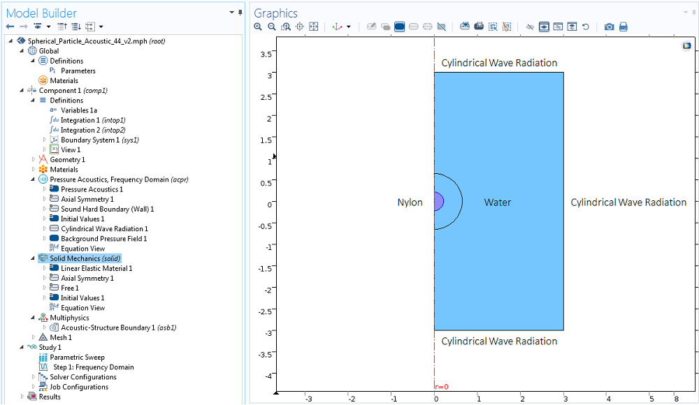
To benchmark the method presnted by Glynne-Jones et al., let’s compute an acoustic radiation force exerted by a standing wave on a spherical nylon particle immersed in water. We assume a frequency of 1 MHz and a pressure amplitude of 1 bar and implement the model using the Acoustic-Structure Interaction interface in 2D axisymmetric geometry. The size of the box in the model is four wavelengths high and two wavelengths wide.
Let’s excite a standing wave in this box using a Background Pressure Field condition, set up in such way that the particle is at a distance of \lambda/8 from the pressure node.

The integrals in Eq. (5) are computed by setting up integration coupling operators in the Component 1 > Definitions node. We need to make sure that the integral is calculated in the revolved geometry by checking the appropriate box and selecting the boundaries of the particle to define the surface of integration.
It is noteworthy to mention here that the force computation used in this method is independent of the surface of integration due to the conservation of flux as long, as it is located outside the particle. In fact, using a surface at larger distances will be more numerically accurate, simply because there will be more points to use for numerical evaluation of the integral. To perform this integration, we can add another surface external to the particle.

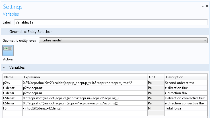
Finally, new flux variables are introduced in the Component 1 > Definitions as Variables 1a node. They are used as arguments for the integration operators to compute the total force.
Comparing the Results to an Analytical Solution
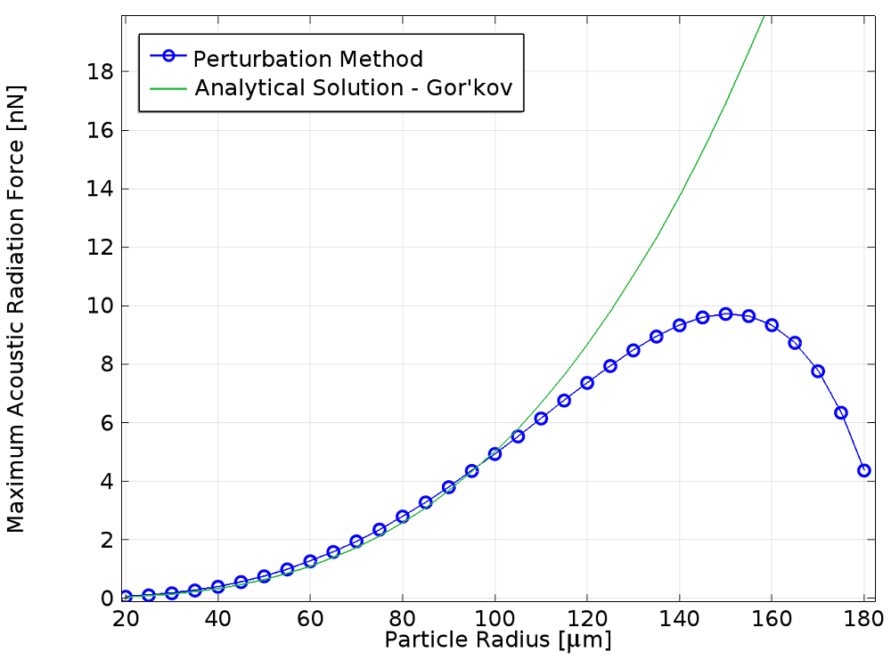
We are now ready to compare the perturbation approach to an analytical solution.
As expected, they compare reasonably well for small particle radii where the analytical solution considered is valid. Some analytical models that include higher harmonics in scattered field decomposition offer solutions that agree with the outlined numerical approach for large and small spherical particles (as in the paper by T. Hasegawa, “Comparison of two solutions for acoustic radiation pressure on a sphere“.)
A small discrepancy for small particle radii between analytical and numerical methods may be attributed to the fact that the theoretical models assume that the particle is plastic, whereas in this example, we have considered an elastic particle with bulk modulus of 0.4.

Concluding Remarks
The perturbation method has a number of advantages.
First, it exploits the linear acoustics method to evaluate nonlinear second-order force effects. This allows the analysis to be easily extended to 3D for particles of arbitrary shapes and material composition. For example, we can extend it to simulate acoustic radiation forces on biological cells or microbubbles.
Second, because the acoustic equations are solved in the frequency domain where very efficient numerical methods are well established, the solution time in COMSOL Multiphysics is quite fast even in 3D.
Meanwhile, the disadvantage of this method is that it is driven by theoretical results that rely on a set of simplifying assumptions, and it can only be validated in a limited number of cases. What we would like to have is a numerical method that allows the problem to be solved directly.
We shall see how this can be achieved in the next blog post. Stay tuned!
Other Posts in This Series
- Direct FSI Approach to Computing the Acoustic Radiation Force
- Modeling Acoustic Orbital Angular Momentum
Further Reading
- Blog posts:
- Model: Acoustic Levitator
- L. V. King, “On the acoustic radiation pressure on spheres“, (1934)
- M. Settnes and H. Bruus, “Forces acting on a small particle in an acoustical field in a viscous fluid“, Phys. Rev. E 85, 016327 1-12 (2012)
- P. Glynne-Jones, P. P. Mishra, R. J. Boltryk, and M. Hill, “Efficient finite element modeling of radiation forces on elastic particles of arbitrary size and geometry“, J. Acoust. Soc. Am., 133, 1885-93 (2013)
- P.B. Muller, R. Barnkob, M.J.H. Jensen, and H. Bruus, “A numerical study of microparticle acoustophoresis driven by acoustic radiation forces and streaming-induced drag forces“, Lab Chip 12, 4617-4627 (2012)
- P.B. Muller and H. Bruus, “Numerical study of thermoviscous effects in ultrasound-induced acoustic streaming in microchannels“, Phys. Rev. E 90, 043016 1-12 (2014)


Comments (2)
Shengping Mao
September 1, 2015Hi Alon Grinenko,
Very interesting and helpful work, thanks.
I try to implement a similar one followed by your instructions. However I find that if I choose the integration over the surface of the particle or the surface larger than the particle, the result is different.
No matter how I play the mesh sizes, I never get a correct force by the integration over the surface of the particle. I noticed you used the integration at the surface larger than the particle. If I use the same way, I will also get a correct force. But I should have the same results no matter which surface I use when I do the integration.
Do you have any comment about it?
Best regards, Shengping
Hakan Çaldağ
July 24, 2019The question Shengping Mao asked is very old but in case someone else is confused about the same thing, I would like to write my own interpretation. The model should give the same force as long as the integration surface is outside the particle. However, when one attempts to take integration over the particle surface, I think that it is against the momentum flux calculation that this article is based on, as there is no possible momentum flux towards inside of the particle. This is why a different result is obtained. I am not sure but that integration could correspond to the case of a fixed, rigid particle as the integration boundary is assumed to be constant. The reason a larger sphere is taken as integration surface is to account for the small vibrations of the free particle due to the acoustic wave anyway. You can compare the values of the components, f1densz and f2densz for the integration boundaries outside the sphere and around the sphere.