
If you want to create an animation from your simulation results, the COMSOL Multiphysics® software offers a variety of powerful and flexible options. In this blog post, we will explore the idea of creating a nontrivial animation by combining slices along the azimuthal direction for a 3D model.
Creating Animations Along the Azimuthal Direction
In many physical scenarios, the dependent field variables could change significantly around a solid object. Let’s consider the Acoustic Scattering off an Ellipsoid tutorial model, where the acoustic pressure field is a function of the azimuthal direction. For such cases, you might want to visualize the solution along the azimuthal direction (as shown in the schematic below).
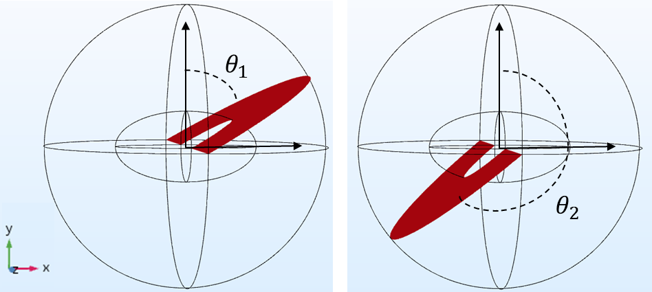
Schematic showing slices at azimuthal angles θ1 and θ2.
Today, we will go over how to plot dependent variables at a given azimuthal angle and further combine the solution slices for various azimuthal angles to create an animation.
How to Create a Slice Plot and Animation in COMSOL Multiphysics®
You can create an animation by combining slices (corresponding to various theta values) in the azimuthal direction using a three-step process. Let’s see how…
Step 1: Defining Theta
First, add a parameter that corresponds to the azimuthal angle theta. Right-click the Results node, select Parameters, and define theta.

Defining theta under the Results node in the Parameters table.
Step 2: Adding a Parameterized Surface
Next, add a Parameterized Surface data set to create a slice at a particular azimuthal angle theta. Under the Results node, you right-click Data Sets and select Parameterized Surface from the submenu More Data Sets.
In the Settings window for Parameterized Surface, Study 1/Solution 1(2) can be used as the data set and result parameter theta defines the expression along the x-, y– and z-coordinates. Note that the Study1/Solution1 (2) data set excludes the solution in the perfectly matched layer (PML). Both solutions, Study1/Solution1 (1) and Study1/Solution1 (2), are exactly the same for non-PML domains.
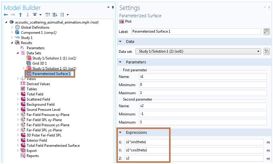
Settings for the Parameterized Surface data set.
Note that you can enter any mathematical expression in the surface parameters s1 and s2 for other types of parametric surfaces.
You can plot the total acoustic pressure field on this parameterized surface using the settings shown in the screenshot below.
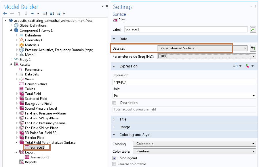
Settings for plotting the total acoustic pressure on a parameterized surface.
The resultant plot for the total pressure field at a prescribed azimuthal angle is displayed below. You could easily change the theta value in the Parameters table of the Results section to visualize the slice solution at a different azimuthal angle.
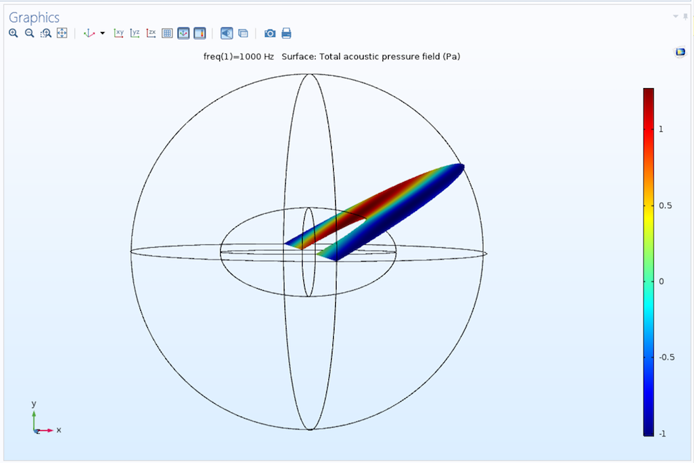
Total acoustic pressure field plotted on a parameterized surface.
Step 3: Generating the Animation
Finally, generate an animation that combines the solution for various azimuthal angles (as defined by theta). To do so, add an Animation node by right-clicking Export under the Results node and then choosing Animation.
In the Settings window for Animation, choose Total Field Parameterized Surface as the Subject, which is the plot shown above at a specific theta value.
Now, change the Sequence type to Result parameter, with theta as the parameter ranging from 0 to 360 degrees, as shown below.
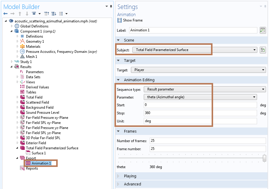
Animation settings to vary the azimuthal angle (theta) values.
Using the above settings, you can visualize the resulting animation in the Graphics window by clicking on the play button (in the Graphics toolbar). The animation is shown below (featuring modified view and annotation plot settings not mentioned here). You can find more details on using annotation plots in 2D or 3D plot groups in a previous blog post.
Animation showing the total acoustic pressure variation in the azimuthal direction.
This process could be extended to any 3D model. The following animation shows the same approach applied to a tutorial model on the thermal modeling of an Li-ion battery.
Animation showing the azimuthal variation in the temperature for a lithium-ion battery.
Summary
The COMSOL Multiphysics software has a diverse set of postprocessing tools to create custom animations. This blog post outlines a simple approach to create animations by combining slices along the azimuthal direction. A similar idea was presented in a previous blog post on combining parallel slices along a Cartesian direction. We will continue to explore more custom animation options in the future, so stay tuned!
If you have not tried creating an animation in COMSOL Multiphysics, check out a tutorial video on creating and exporting standard animations by clicking the button below.


Comments (0)