
The Application Builder is a powerful tool for transforming models into customized, easy-to-use apps. An app’s intuitive user interface (UI) not only gives you control over simulation inputs and geometric parameters, but it also enables you to program the app to perform complex operations. Today, we’ll demonstrate how to create an app that allows you to dynamically create or modify geometry parts and apply appropriate physical specifications and mesh, all thanks to the power and flexibility of the Method Editor.
A Concrete Example: Induction Heating of a Steel Billet
To illustrate how to dynamically modify geometries in numerical modeling apps, we will use our Induction Heating of a Steel Billet demo app. The purpose of this app, which you can download from the Application Gallery, is to design an induction heating system for the reheating of steel billets (bars) in the context of a manufacturing process like forging.

Induction heating is a contactless heating method that uses an electromagnetic field. Image licensed under CC BY-SA 3.0, via Wikimedia Commons.
The app itself is an interesting and useful tool for simulating induction heating, a contactless heating method that involves applying an AC electromagnetic field to a conductive part in order to heat it up. While its industrial applications are of interest, we will focus here on using it as an example to illustrate how to control the model geometry and setup of an app with the functionality available in the Application Builder.
Let’s take a look at the schematic below. Here, we have a heating system that consists of one or more circular coils, driven with an AC current, that are aligned along a common axis at specified distances. The billet travels at a constant velocity along the axis and is heated by the AC electromagnetic field generated by the coils as it passes through them.
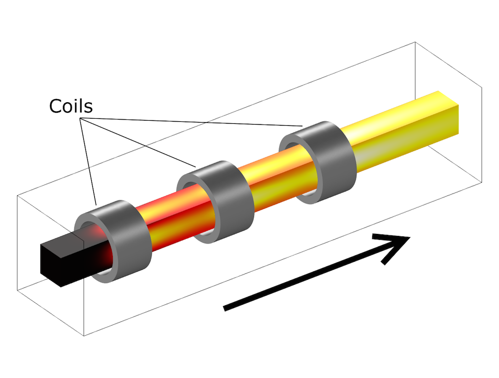
The billet is heated as it travels through the coils.
When it comes to the results of the heating process, there is an array of factors that can have an impact. The initial temperate of the billet, its translational speed, the magnitude of the exciting current, and the configuration of the coils (their number, size, and placement) are just some examples.
When designing an app for this type of simulation, it is important to enable greater flexibility as to what aspects of the heating system can be specified so that app users can easily test different configurations. In particular, the app must be able to control the model geometry. We can achieve this by combining the flexibility of geometry parts with the expressive power of the Method Editor.
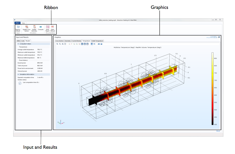
The UI of our Induction Heating of a Steel Billet demo app.
Dynamically Adding Geometry Parts
Geometry parts are “building blocks” that can be defined once and then used (and reused) in the construction of a geometry. The parts can be parameterized using local parameters, which work exactly like model parameters but only within the context of the geometry part.
Geometry part definitions are collected in a dedicated node under Global Definitions in the Model Builder tree. Since we want our app to allow the addition of multiple coils, it is natural to create a geometry part that represents the individual coil. The part itself is rather simple: two concentric cylinders with the same length, and all of its geometrical aspects, from length to the inner and outer radius, are expressed by means of local parameters. We can add copies (instances) of the part in the model geometry using a Part Instance node that references the definition.
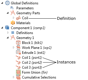
Geometry parts are defined under Global Definitions and can be used multiple times in a geometry.
When users click the Update Geometry button, the app will execute a method that updates the geometry according to the specification. The method is written using Java® code and can be readily inspected by opening the app in the Application Builder. For the sake of clarity, we will illustrate such functionality using a simplified version of the code.
Let’s start with the basics. First, we’ll want to modify the existing model geometry by adding a part instance and linking it to the Part definition containing the coil. The following code snippet does just that:
model.geom("geom1").create("pi1", "PartInstance");
with(model.geom("geom1").feature("pi1"));
  set("part", "coil");
endwith();
The code references precisely all of the nodes in the tree by their tags: pi1 represents the newly created part, geom1 represents the geometry in which it is created, and so on. Fortunately, you don’t have to look up the tags when you are writing the code; in fact, you don’t have to write any code at all! Simply click on the Record Code button in the Method Editor toolbar, go to the Model Builder, and add a part instance to a geometry as you normally would when building a model. A fragment, similar to that shown above, will be automatically added to the method.
First time using the Record Code feature? Consult this blog post for guidance.
These operations are enough to create a part instance in the geometry. However, we want to add as many part instances as the user specifies. We can readily accomplish this with a for loop, which repeats the above operations multiple times. Assuming that there is an Integer declaration named numCoils that specifies the number of coils, the code should be updated as follows:
for (int i = 0; i < numCoils; i++) {
  String tag = "part"+(i+1); // Create a unique tag for each part

  model.geom("geom1").create(tag, "PartInstance");
  with(model.geom("geom1").feature(tag));
    set("part", "coil");
  endwith();
}
Note how the tags of the part instances are constructed dynamically so as to ensure uniqueness. Applying specifically crafted tags will prove to be useful in a later step as well.
Our method now creates a number of part instances that are consistent with the specification every time it is run. But what happens if the method is run twice (i.e., if the user clicks the button twice)? The method will try to construct the part instances once again, using tags that already exist. As the tags must be unique, such behavior produces an error that we need to fix. A simple but effective solution is to remove all part instances that are already present before adding (or re-adding) the new ones. In this case, utilizing a specific format for the part tags comes in handy:
int counter =  1;
String[] tags = model.geom("geom1").feature().tags();   // Tags of the existing nodes in the Geometry
while (contains(tags, "part"+counter)) {
  model.geom("geom1").feature().remove("part"+counter);
  counter++;
}
This fragment of code must be placed just before the code that creates the parts. The for loop will test if there are geometry features with tags that match the format we used when creating our parts and delete the ones that it finds. As an exercise, you may want to try to make this code “smarter” so that it reuses the existing parts constructed in a previous execution of the method.
Positioning the Part Instances
Our app now dynamically creates parts of the geometry. But to make these parts useful in a simulation, we need to place them in the proper position. One way to implement such functionality in an app’s design is to let users specify the x-coordinates of the individual coils in an array.
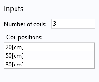
An app’s very simple UI that enables users to enter information about the coils.
The UI control utilizes an Array 1D String definition as its source, adding in the data entered by users. We just need to modify our code so that it places the coils accordingly once they are created:
for (int i = 0; i < numCoils; i++) {
  String tag = "part"+(i+1); // Create a unique tag for each part

  model.geom("geom1").create(tag, "PartInstance");
  with(model.geom("geom1").feature(tag));
    set("part", "coil");

    setIndex("displ", coilPositions[i], 0); // Place the part instance at the correct position

  endwith();
}
The command setIndex("displ", coilPositions[i], 0) sets the first coordinate (the one in position 0) of the displ vector to the specified value. Once again, you don’t have to look up the name of the property displ. You can instead use the Record Code feature, or the Editor Tools, to construct the line of code and modify it appropriately.
Specifying the Physics Conditions
Now that we’ve added the parts and positioned them properly, the next step is to dynamically set up the physics so that the correct domain conditions are used. In this specific case, the domain condition that we want to use is the Coil feature, available in the Magnetic Field interface. The operation is similar to that used for the part instances, so we can follow a relatively similar algorithm:
- Remove any old Coil features that may be present in the interface
- Add new Coil features according to user specification
The code that performs these operations is as follows. You will recognize the structure from the code used to create the geometry. The only difference is that it now operates based on physics features.
// Update the physics: remove all old Coil features
counter = 1;
tags = model.physics("mf").feature().tags();
while (contains(tags, "coil"+counter)) {
  model.physics("mf").feature().remove("coil"+counter);
  counter++;
}

// Create new Coil features, one for each coil. Use incrementing tags "coil1", "coil2", etc.
for (int i = 0; i < numCoils; i++) {
  String tag = "coil"+(i+1);
  model.physics("mf").create(tag, "Coil", 3);
}
Setting the Selections
Finally, we need to specify the correct selection for the Coil feature just added, so that each feature is applied to its corresponding part instance. To do so, we can use the Selection of Resulting Entities functionality in the Geometry Part definition.
When this functionality is enabled, each part instance added to the model geometry may generate a selection that encompasses the instance itself and can be used to specify physics conditions. To enable the functionality for the Geometry Part definition, navigate to the last geometry operation in the tree (the Coil node in our example) and select the Resulting objects selection check box in the Selection of Resulting Entities section.
The procedure for selecting each added coil is straightforward:
- Let the part instance also define an instance of the selection by clicking on the Part Instance node and selecting the Keep noncontributing selections check box
- Let the Coil feature utilize the named selection defined by the part instance
By modifying the code as follows, these operations are performed in the app method. In the for loop that creates the parts, add this line:
set("selkeepnoncontr", "on"); // Select the "Keep noncontributing selections" check box
Meanwhile, in the for loop that creates the physics feature, add the following lines:
String partInstanceTag = "part"+(i+1);
model.physics("mf").feature(tag).selection().named("geom1_"+partInstanceTag+"_dif1_dom");
The tags of the selections are geom1_part1_dif1_dom, geom1_part2_dif1_dom, and so on. Therefore, they can be constructed iteratively as shown in the previous fragment. To find the tags that you need, simply use the Record Code feature or the Editor Tools.
The complete method code, after adding some comments and finishing touches, is this:
// Delete all the part instances already present. They are identified by the tags "part1", "part2", etc.
int counter = 1;
String[] tags = model.geom("geom1").feature().tags();
while (contains(tags, "part"+counter)) {
  model.geom("geom1").feature().remove("part"+counter);
  counter++;
}

// Create new Part Instances, one for each coil. Use incrementing tags "part1", "part2", etc.
for (int i = 0; i < numCoils; i++) {
  String tag = "part"+(i+1); // i starts from zero, but the tags must start from "part1".
  model.geom("geom1").create(tag, "PartInstance");
  with(model.geom("geom1").feature(tag));
    set("part", "coil"); // Use the coil geometry

    set("selkeepnoncontr", "on"); // Keep noncontributing selection, so that they can be used in the physics features

    setIndex("displ", coilPositions[i], 0); // Specify the position according to the coilPositions vector.
  endwith();
}

// Update the length of the billet and the air box - 50 cm longer than the last coil position
model.param().set("airbox_length", "("+coilPositions[numCoils-1]+")+50[cm]");

// Build the geometry
model.geom("geom1").run();

// Update the physics: remove all old Coil features
counter = 1;
tags = model.physics("mf").feature().tags();
while (contains(tags, "coil"+counter)) {
  model.physics("mf").feature().remove("coil"+counter);
  counter++;
}

// Create new Coil features, one for each coil. Use incrementing tags "coil1", "coil2", etc.
for (int i = 0; i < numCoils; i++) {
  String tag = "coil"+(i+1);
  model.physics("mf").create(tag, "Coil", 3);

  // Set the new Coil feature selection: use the named selection added by the Part Instance
  String partInstanceTag = "part"+(i+1);
  model.physics("mf").feature(tag).selection().named("geom1_"+partInstanceTag+"_dif1_dom");
}
By clicking the Run Application button, you can easily test out the app. During testing, you can save the current state of the app for further analysis by simply selecting Save As from the app’s File menu.
Designing More Dynamic Numerical Modeling Apps
Using an induction heating example, we have shown you how to dynamically manipulate the geometry and physics in apps via geometry parts and the Method Editor — another testament to the power and flexibility of the Application Builder. This particular example also includes other advanced functionality that you may want to learn about and include in your own apps, such as importing geometry parts from other files and visualizing the 2D cross section of the billet before creating the 3D geometry. Download the demo app presented here from our Application Gallery to learn more.
For further guidance and inspiration in designing apps, browse the resources highlighted below.
Inspiration and Guidance in Building Apps
- New to the app-building process?
- Use our Intro to Application Builder Videos series as helpful starting point
- Looking to advance your app designs?
- Learn how to implement advanced geometry in your app by reading this blog post
- Get helpful tips and tricks for enhancing the structure and user workflow of your apps:
- Want to gain hands-on experience building apps? Attend one of our free workshops
- Have additional questions related to designing apps or incorporating functionality into their design? Contact us today
Oracle and Java are registered trademarks of Oracle and/or its affiliates.


Comments (2)
Loïc Prince
July 6, 2017Hi Andrea,
I have created a geometry with random spheres in a cube, and I want to assign a material for one part of the spheres and another material for the other part. The fact is that I have a lot of spheres and I can’t do the selections manually, so I would like to make it automatically. I have tried to adapt the code above, but I don’t succeed and I don’t know if it’s possible.
Could you help me to fix that ?
Thank you in advance
Andrea Ferrario
July 19, 2017 COMSOL EmployeeHello!
The strategy I described in the article can only be used if you are adding Geometry Part instances to your geometry.
If you are adding the spheres directly to the geometry as geometry objects, you can instead use Cumulative Selections to create selections that automatically collect all the spheres. Check the Reference Manual and the Programming Reference Manual for more information.
You can also have a look at this blog post, which describes a model seemingly similar to the one you describe: https://www.comsol.com/blogs/how-to-create-a-randomized-geometry-using-model-methods/
I hope you will find this useful! If you still have difficulties, please contact support at https://www.comsol.com/support .