
Thermostats are used in most homes for controlling furnaces and air conditioners to maintain a comfortable interior temperature. A simple thermostat controlling a heater will have on and off setpoints. Such a control scheme is easy to implement within COMSOL Multiphysics using the Events interface, as presented in a previous blog post. Today, we will expand this technique to include a delay, a time lag between turning the heater on or off, in a thermostat simulation.
Why Thermostats Use a Delay
The typical home thermostat for your furnace or heater has two temperature setpoints:
- On, at which the heat is turned on at the maximum possible rate
- Off, at which the heat is turned off
In practice, you may only directly control one of these setpoints, with the other setpoint automatically set to a few degrees different. Such a control scheme can be modeled with the approach developed in a previous blog post on thermostats. Today, we will include a time delay between switching the heater state in our thermostat simulation.
A delay can be implemented for many reasons, but one of the main reasons is to prevent short-cycling of the heater. Turning a device on and off repeatedly can lead to excessive wear on the system components, which will incur repair costs that we want to avoid.
There are various different delay schemes that we can use to prevent short-cycling. One common approach is to maintain the heater in either the on or off state for some defined minimum time before switching. Let’s look at how this control scheme is implemented within COMSOL Multiphysics.
Implementing a Thermostat with Delay in COMSOL Multiphysics
Let’s suppose that you have a thermal model of a house or any other system wherein you want to control a heater using a thermostat with a delay. Within such a model, you can choose one point as the location of the thermostat temperature sensor, as described in our earlier blog post on modeling thermostats. As previously mentioned, we will use the Events interface to control the on/off state of the heater in our model.
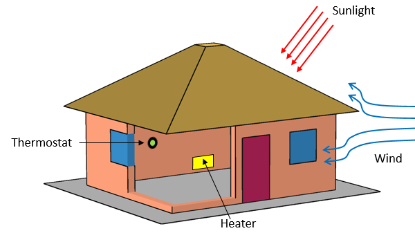
A thermal model of a house. The thermostat monitors the sensor temperature and controls the heater’s on/off state.
Before we get to the implementation, let’s write out exactly how we want our thermostat to work. We have a thermostat with an upper and lower setpoint and we want the heater to maintain its current state, either on or off, for a specified delay time. We can write this as two separate statements:
- If the heater has been in the off state for more than the specified delay time and if the temperature is below the lower setpoint, then turn the heater on.
- If the heater has been in the on state for more than the specified delay time and if the temperature is above the upper setpoint, then turn the heater off.
These two statements can be implemented within the Events interface. We simply need to introduce a way to track the time that has elapsed since the last switching of the thermostat. The screenshots below show how to set up these conditions.
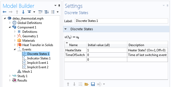
The Discrete States interface defines two discrete variables that determine the heater state.
The Events interface contains several features, starting with the Discrete States interface shown in the screenshot above. Two discrete variables are defined: HeaterState and TimeOfSwitch. The HeaterState variable is initially one, meaning that at the start of the simulation, the heater is turned on. This variable is used within the Heat Transfer in Solids interface as a multiplier on the applied heat load. To turn the heater off, the HeaterState variable is set to zero instead. The TimeofSwitch variable stores the time of the last switching event. For this problem, the initial value is zero, which means that at t=0, the heater state was switched.
These two Discrete State variables are only changed when an event is triggered, and for this to happen, we need to check the elapsed time since the last switching event, and we need to check the temperature of the sensor against the upper and lower setpoints. This is done with the Indicator States interface, as shown in the screenshot below.
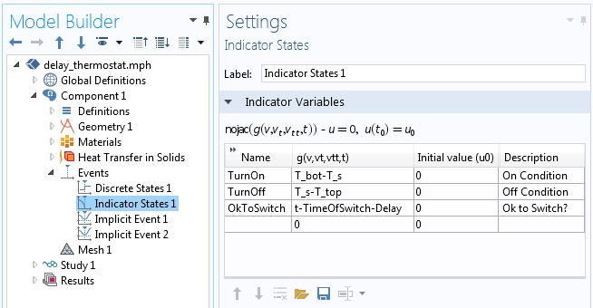
The Indicator States interface defines three different indicators that will trigger an event.
We can see in the above screenshot that three different indicators are tracked during the simulation. First, the TurnOn indicator evaluates the expression T_bot-T_s, which will go from negative to positive when we want to turn the heater on, where T_bot is a Global Parameter. The variable T_s is the sensor temperature and is defined using a Point Integration Coupling and a Variable Definition, as described in our earlier blog post on thermostats. Similarly, the TurnOff indicator evaluates T_s-T_top and goes from negative to positive when we want to turn the heater off.
The OkToSwitch indicator evaluates t-TimeOfSwitch-Delay and goes from negative to positive after the heater is either in the on or off state for longer than the specified delay time, where Delay is also a Global Parameter. These discrete and indicator states are used to trigger two Implicit Events, as shown in the following screenshots.
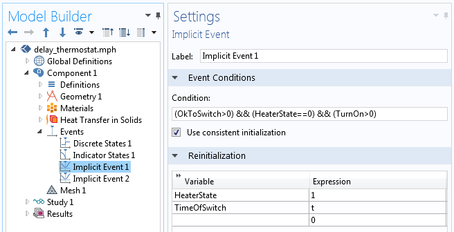
The first Implicit Event controls when the heater is turned on.
In the above screenshot, the first Implicit Event is used to turn on the heater. The Event Condition is: (OkToSwitch>0)&&(HeaterState==0)&&(TurnOn>0). This logical condition can be read as: If the time since the last switching event is greater than the specified delay time, and if the heater is currently off, and if the sensor temperature is below the turn on setpoint, trigger an implicit switching event. When this event is triggered, the solver is restarted and reinitializes HeaterState to one, which turns on the heater. Additionally, TimeOfSwitch is reinitialized to t, the current time. These two variables will remain unchanged until another implicit event is triggered.
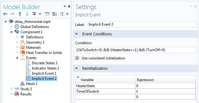
The second Implicit Event controls when the heater is turned off.
The second Implicit Event, shown above, is almost identical to the first, but instead triggers a turn-off event. When the condition (OkToSwitch>0)&&(HeaterState==1)&&(TurnOff>0) is satisfied, this event reinitializes HeaterState to zero and TimeSinceSwitch to the current time.
You may ask yourself why, in these two implicit events, we check if the heater is off before triggering it to turn on (and similarly check if the heater is on before we trigger it to turn off). This additional check is done to prevent any events from getting triggered and reinitializing TimeOfSwitch too often. The system may naturally (due to some change or fluctuation in the other boundary conditions) get into a state where the sensor temperature goes above the upper setpoint without any heating. Or, the sensor temperature could stay below the lower setpoint even though the heater is on. We do not want such cases to result in any events being triggered, hence these additional checks.
With these features as just described, we have implemented our thermostat with delay between switching. Before solving, make certain that the initial values of the Discrete States, the HeaterState and the TimeOfSwitch variables, are appropriate for the initial heater state, and the last switching event. Also keep in mind that you may need to adjust the Event Tolerance, as demonstrated in our previous blog post on thermostats.
Let’s now look at some results.
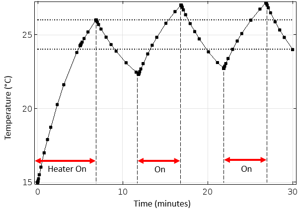
The thermostat with delay can switch only every five minutes. The horizontal dashed lines represent the thermostat setpoints.
In the above plot, we can observe the thermostat delay behavior. The sensor temperature is initially below both setpoints and the heater is switched on at the time of zero. The system takes about seven minutes for the sensor temperature to reach the upper setpoint, at which time the heater turns off. The system starts to cool down quite rapidly, but the thermostat cannot switch back on until five minutes have elapsed. The thermostat temperature dips below the lower setpoint before the heater switches back on. After the heater is switched on, the system temperature rises above the upper setpoint, again due to the five-minute switching delay time. We can observe this over- and under-shoot behavior repeating in time.
Closing Remarks on How to Implement a Delay in Your Thermostat Simulation
The technique we’ve outlined here will enable you to implement a thermostat model with a delay between any switching events and is representative of many real control schemes. The key difference for implementing a delay in your thermostat simulation versus a thermostat without delay is the introduction of an additional Indicator State variable that keeps track of the thermostat switching time.
Of course, this approach is useful far beyond just temperature control. Within COMSOL Multiphysics, we can use the Events interface whenever we solve a transient problem.
- If you have additional questions about this technique, or would like to use COMSOL Multiphysics for your modeling needs, please don’t hesitate to contact us
- Read these related blog posts for more information on the Events interface and thermal modeling of a house:


Comments (0)