
In a previous blog post, we discussed how parametric geometries of roller chain sprocket assemblies can be built effortlessly using the built-in geometry parts in the Part Library in the COMSOL Multiphysics® software. In this second part of our chain drive modeling blog series, you will learn how this geometry can be used as an input to automatically generate a model setup for analyzing a chain drive system.
What Are the Challenges in Chain Drive Modeling?
As we already discussed, a chain drive is an assembly of several links wrapped around one or more sprockets, used to transfer power from one component of a machine to another. Because of the large number of components with different types of interactions, the dynamics of such a system is not trivial to simulate. To get a flavor of the challenges that you might face while modeling a chain drive system, let’s analyze a chain drive mechanism from a modeling perspective.
Consider chain links or sprockets that are made of metal or any other stiff material that undergoes negligible deformation during operation. In such cases, you can judiciously assume them as rigid bodies. To model rigid bodies in COMSOL Multiphysics, you need to add a Rigid Domain node on each of the links. Another important aspect to consider while modeling is the ability of links to rotate about the joint axis, which allows them to move and slide over the toothed sprocket. For modeling this unrestrained rotation between two links, two Attachment nodes on each of the link boundaries and one Hinge Joint node between them are required. Similarly, to model the contact dynamics between sprockets and links, you need to add a Contact node between the outer boundaries of each of the sprockets and links.
For a system with multiple chain links and sprockets, manually adding such physics nodes with proper parameters, for example the axis and center of rotation for each hinge, is an exhausting task with a high chance of manual errors.
Editor’s note on 12/13/22: In version 6.1, the Rigid Domain feature has been renamed to Rigid Material.
How to Model Chain Drives with the Multibody Dynamics Module
For quickly setting up a chain drive system, COMSOL Multiphysics introduced a new functionality in version 5.5. With the Chain Drive feature available in the Multibody Dynamics interface, you can easily generate several physics nodes required for analyzing the system from a single click of a button. Using a set of input parameters, it is also possible to simulate some commonly observed effects, like the presence of elastic bushings between chain links, occurrence of losses in link joints, etc. In the following sections, we demonstrate the details of the Chain Drive functionality with two interesting examples.
The prerequisite for setting up a chain drive model is a realistic system geometry. You can create the chain geometry either in COMSOL Multiphysics or in any CAD tool. Once a chain sprocket assembly geometry is available, the next step in modeling is to add the Chain Drive node in the Multibody Dynamics interface.
After adding the Chain Drive node, the Model Builder looks like the figure below:
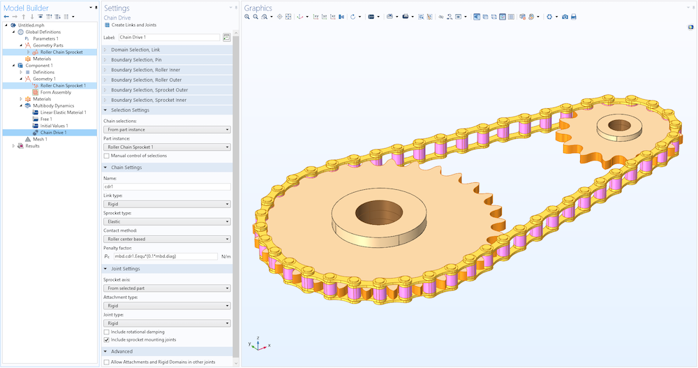
The Model Builder with a roller chain sprocket from the Part Library added as a part instance in the geometry. This part instance is taken as an input by the Chain Drive node in the Multibody Dynamics interface to create various physics features.
The Chain Drive node automates and thereby simplifies the model setup with the help of a button, namely, Create Links and Joints, located at the top of the Settings window. With the click of this button, multiple node groups containing physics feature nodes such as Rigid Domain, Attachment, Hinge Joint, and Contact are added in the Model Builder. It is important to note that there are different inputs that you need to set before pressing the Create Links and Joints button. These inputs are required to set proper selections and other parameter values to the autogenerated physics nodes. The following sections describe different inputs and how to tune them to suit your various modeling requirements.
Selection Settings for the Chain Drive Node
The most important input required for the Chain Drive node to generate several physics nodes is a set of domain and boundary selections. You can input these selections either manually or automatically using the Chain selections input. If Chain selections is set to User defined, you need to create appropriate selections on different components of your roller chain geometry and input them to the respective selection input fields.
The easiest alternative to this manual method is to use the From part instance option. When Chain selections is set to From part instance, the Part instance input lists all of the available geometries of the roller chain in the Geometry node (see figure below). As mentioned in the previous blog post, the built-in parts for the roller chain sprocket assembly contain a set of predefined selections. When a particular roller chain geometry is selected, all of its predefined selections are automatically identified and taken as the input required for the Chain Drive. Since the selection inputs are automatically set, they are in a noneditable state. However, you can edit them by selecting the Manual control of selections check box if needed.
The different domain and boundary selection inputs available in a Chain Drive are as follows:
Domain Selection Inputs
As shown in the figure below, a Chain Drive can have a maximum of three domain selection inputs:
- Domain Selection, Link
- Domain Selection, Sprocket
- Domain Selection, Bushing
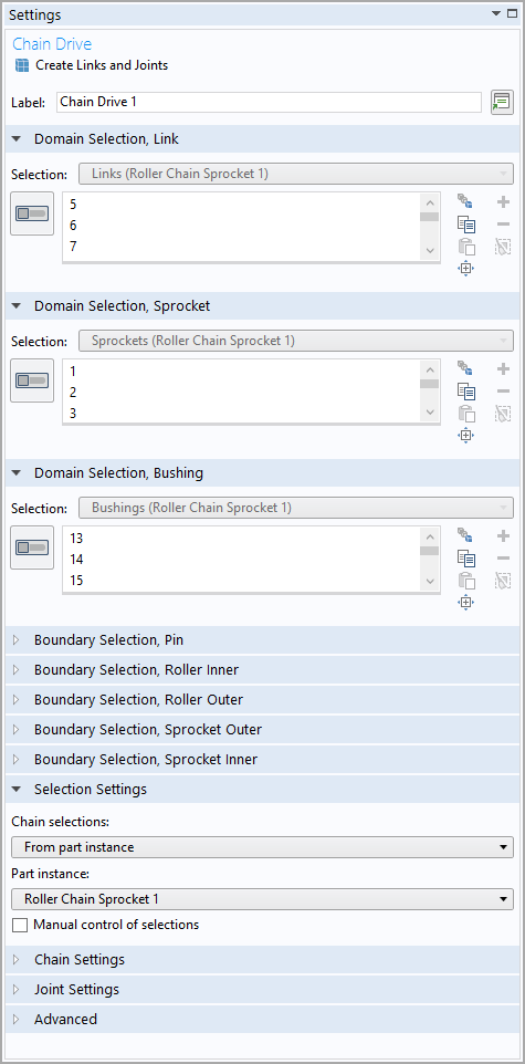
Different domain selection inputs in the Chain Drive node.
It is not necessary that all of the selection inputs are available all of the time; rather, they appear conditionally depending on other model parameters. For example, if you want to model all of the links in your chain as rigid bodies, set the Link type input to Rigid. In this case, the selection input Domain Selection, Link would be available. Using this selection input, Rigid Domain nodes are created on each of the link plates. If you use a geometry from the Part Library, a built-in domain selection named Links is automatically selected here. If you are using your own geometry, you need to input a domain selection containing all link plates.
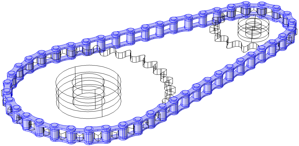
Selection of all the link plates used for creating Rigid Domain nodes.
For modeling rigid sprockets, the selection input Domain Selection, Sprocket is used. Similar to link domain selection, this input is available only when the Sprocket type is set to Rigid. If you use a geometry from the Part Library, a built-in domain selection named Sprockets is automatically selected. If you are using your own geometry, you need to input a domain selection containing both sprocket domains.
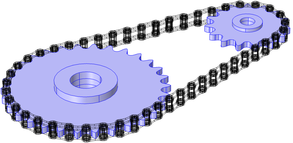
Selection of both sprockets used for creating Rigid Domain nodes.
The third domain selection input, Domain Selection, Bushing, is used when you want to include the effect of elastic bushings between rigid links. In such cases, set Link type to Rigid with elastic bushings. An additional selection input, namely, Domain Selection, Bushing, would appear where you can input the bushing domains. While keeping the links as rigid, this will add the Linear Elastic Material node on all of the bushing domains between links. If you use a geometry from the Part Library, a built-in domain selection named Bushings is automatically selected. If you are using your own geometry, you need to input a domain selection containing all bushing domains.
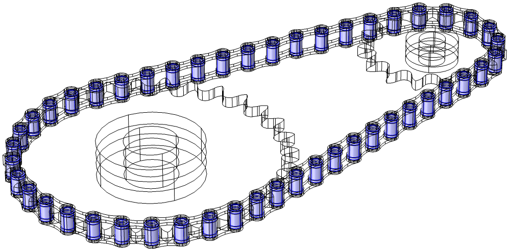
Selection of bushing domains used for creating the Linear Elastic Material node.
If you are interested in the elastic deformations and subsequent stress distributions in links and sprockets, the system components need to be modeled as elastic bodies. This is possible by setting the values of Link type and Sprocket type to Elastic. In such cases, no rigid domains need to be added, hence the corresponding domain selection input would be hidden. The bodies would be modeled using the default material model, Linear Elastic Material, in the Multibody Dynamics interface.
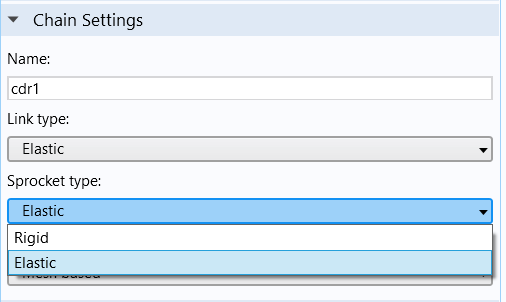
The Chain Settings section in the Chain Drive node, with parameters to create rigid or elastic bodies.
Boundary Selection Inputs
There are a maximum of five boundary selection inputs that a Chain Drive node can have. Like domain selection inputs, some modeling conditions may not require some boundary selection inputs. Those would be hidden, and the rest will be available in the Settings window.
The boundary selection inputs in a Chain Drive are:
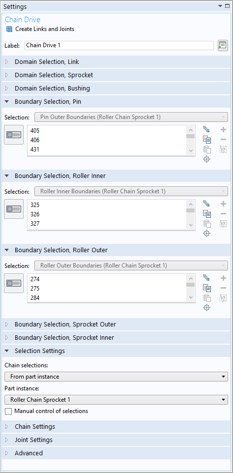
- Boundary Selection, Pin
- Boundary Selection, Roller Inner
- Boundary Selection, Roller Outer
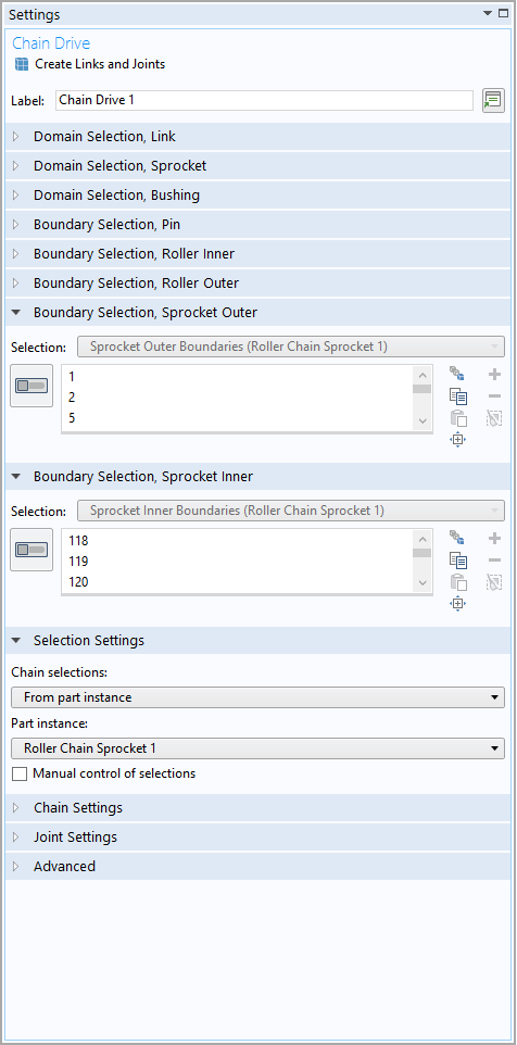
- Boundary Selection, Sprocket Outer
- Boundary Selection, Sprocket Inner
Different boundary selection inputs available on chain links (left) and sprockets (right).
The boundary selection inputs are mainly used to create physics nodes such as Attachment, Hinge Joint, and Contact. In the following sections, which describe joint and contact modeling, you will see how different boundary selection inputs are used to create selections for corresponding features.
Joint Settings in Chain Drives
In a chain, the connection between adjacent link plates (roller plates and pin plates) is designed in such a way that the relative rotation between them is unrestricted. This behavior can be captured in the model with a Hinge Joint with axis normal to the plane of the geometry. The selection inputs Boundary Selection, Pin and Boundary Selection, Roller Inner are used for this purpose. An Attachment node is created on each of the mating pin plate outer boundaries and roller plate inner boundaries. These attachments are used as the Source and Destination inputs for the Hinge Joint created between them.
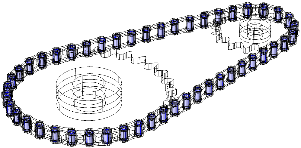
The selection on pin plate boundaries used for creating Attachment nodes. The roller inner boundaries selection is also at the same geometrical position.
To easily control and set some important parameters of the autogenerated Attachment and Hinge Joint nodes, the Chain Drive node provides some settings in the Joint Settings section. For example, one important parameter for Attachment is its connection type. It can be either rigid or flexible. By changing the Attachment type input of the Chain Drive node to Rigid or Flexible, you can set the Connection type of all Attachment nodes to your desired value.
Similarly, for setting the values of the axis and elasticity of multiple Hinge Joint nodes at a time, use the Sprocket axis and Joint type inputs. If you were using the built-in parts for geometry, the axis of all joints would be the same as the part’s sprocket axis. You can change this either by specifying a direction or by selecting an edge parallel to the sprocket axis. By setting Joint type to Elastic, it is also possible to add an elastic connection between attachment surfaces.
Another important aspect that can be included in joints through the Chain Drive node is the rotational damping. By selecting the Include rotational damping check box and setting the proper value of the Damping coefficient, you can incorporate the effect of viscous damping in all of the joints.
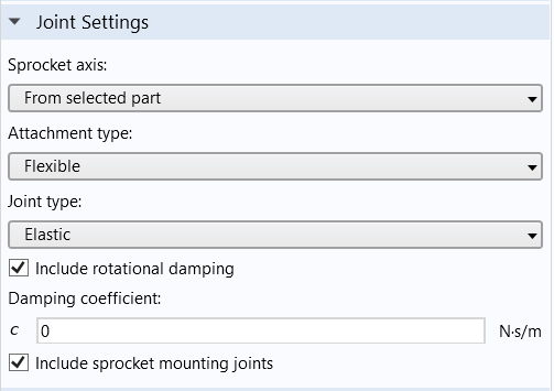
The Joint Settings section in the Chain Drive node, with parameters to control the Hinge Joint and Attachment nodes.
If the chain drive system is mounted on some external shafts, you may need to create attachments and hinge joints on the sprocket to connect them. If the check box in Joint Settings is selected, the Chain Drive node automatically creates an Attachment node and a Hinge Joint node for each sprocket.
Modeling Contact in Chain Drives
When the chain moves over sprockets, the outer boundaries of the chain links and sprockets come into contact. Hence, to model the contact dynamics of the chain drive system, selections on the outer boundaries of the roller plates and sprockets are required. The two selection inputs, namely Boundary Selection, Roller Outer and Boundary Selection, Sprocket Outer, are utilized for this purpose.
Either a mesh-based method or a roller-center-based method is used to model the contact. In the mesh-based method, a Contact Pair between the outer boundaries of the rollers and sprockets is created and a Contact node with Penalty formulation is added to compute the contact forces between the contact pair surfaces.
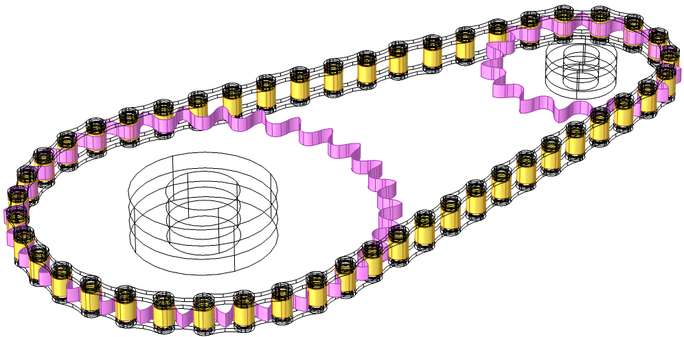
Contact pair between the outer boundaries of rollers and sprockets.
Instead of using a computationally expensive mesh-based method, a faster version of the penalty-based contact method is available to analyze systems with rigid roller plates. This method is called the roller-center-based method. Using a General Extrusion operator, this method calculates the gap between the outer boundary of the rollers and the closest point on the sprocket in the direction of the spatial normal.
By now, we understand that the Chain Drive node acts as a “parent node” to generate multiple other physics nodes and set their parameter values. As mentioned earlier, the automated creation of physics nodes is initiated through the Create Links and Joints button. As the “child nodes” take some of their parameter values from the parent Chain Drive node, click the button only after setting appropriate values for all parameters. After the automatic creation of physics nodes, if you change the selections or some other parameters in the Chain Drive node, the settings of the associated physics nodes also require an update. Click the Create Links and Joints button again in order to update the settings of the existing physics nodes or to create new physics nodes. In all such cases, wherever an update is required, a warning message is added under the Chain Drive node to notify you.
Simulating the Dynamics of Roller Chain Sprocket Assemblies in COMSOL Multiphysics®
So far, we have seen how COMSOL Multiphysics provides easy solutions to simplify geometry building as well as for the model setup of a chain drive system. This is demonstrated in the Dynamics of a Roller Chain Sprocket Assembly and Stress Analysis of a Roller Chain Sprocket Assembly models.
The Dynamics of a Roller Chain Sprocket Assembly model simulates the dynamics of a chain with rigid links wrapped around two rigid sprockets in 2D. The geometry of the chain sprocket assembly is created using built-in geometry parts, and the entire model is set up using the Chain Drive node in the Multibody Dynamics interface. The system is set into motion by an angular velocity prescribed at the driver sprocket. A transient study is run to understand the dynamics of the system when the driven sprocket is unloaded or loaded by a counteracting external torque.
Displacement of chain links and sprockets modeled in 2D.
The Stress Analysis of a Roller Chain Sprocket Assembly model shows how to set up 3D models of chain sprocket assemblies. All components are assumed elastic, and the dynamics of the system are initiated via an angular velocity at a sprocket. Chain links transmit motion to the second sprocket, and that sprocket is subjected to an external torque that is counteracting. We perform a transient analysis for the load path, contact forces, and stress distribution for various assembly components.
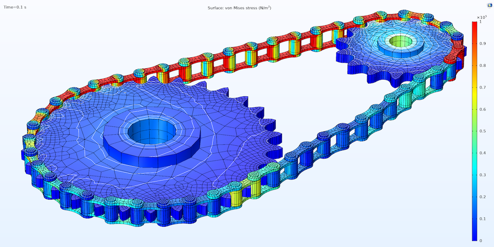
Von Mises stress distribution in the chain drive at t = 0.1 sec.
Next Steps
Try using the built-in geometry parts in the COMSOL Multiphysics Part Library to build your own chain drive geometries. Automate your model setup with the Chain Drive functionality and see the ease in your modeling workflow. Also, explore other new functionalities and improvements available in the Multibody Dynamics Module as of COMSOL Multiphysics version 5.5:




Comments (0)