Resistive and capacitive effects are fundamental to the understanding of electrochemical systems. The resistances and capacitances due to mass transfer can be represented through physical equations describing the corresponding fundamental phenomena, like diffusion. Further, when considering the resistive or capacitive behavior of double layers, thin films, and reaction kinetics, such effects can be treated simply through physical conditions relating electrochemical currents and voltages. Lastly, resistances and capacitances from external loading circuits can easily be represented in the COMSOL Multiphysics® software.
What Are Resistive and Capacitive Currents?
When interpreting the behavior of an electrical circuit, we often speak of resistances and capacitances. Current passing through a resistor with a resistance R (Ω) scales with the applied voltage V, while current across a capacitor with a capacitance C (F) scales with the rate of change of voltage:
In an electrochemical cell, we can apply voltage and measure current, or vice versa. Therefore, the response of the cell is often considered in terms of resistances and capacitances. In AC impedance analysis, the resistive current is in phase with the applied voltage, while the capacitive current is out of phase. While we can recover resistances and capacitances from the measured data, a wide variety of physical effects contribute to the measured currents. Considering the solution to the equations describing the physical processes that cause resistance and capacitance can provide greater physical insight. In this way, we use simulation as a means of fitting measured data, interpreting it in terms of the underlying physical causes.

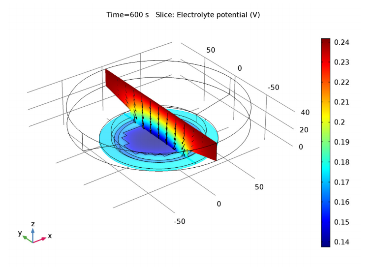
A plot of electrolyte potential (color plot) illustrates the voltage associated with resistance to current flow (black arrows) in a plating cell for electrodeposition on a patterned wafer. The changing resistance of the deposited layer is also included in the model.
Electrochemical Effects that Cause Resistance and Capacitance
Effects interpreted as resistance in an electrochemical cell most often arise due to the finite conductivity of the electrolyte. Passing current through the electrode, between the anode and cathode, requires a certain applied voltage, just like in a conventional resistor in a circuit. The Primary Current Distribution and Secondary Current Distribution physics interfaces in COMSOL Multiphysics solve Ohm’s law to predict the magnitude of this voltage, usually called the ohmic drop, as a function of electrolyte conductivity and electrode geometry.
When electrode reaction kinetics are important, an additional voltage, called overpotential, is required to overcome the activation energy for the electrochemical reaction occurring at an electrode surface. Common electrode reaction kinetic rate laws, such as the Tafel law or Butler-Volmer equations, define the current density in terms of an overpotential — this current-voltage relation can be interpreted as a resistance. However, unlike a simple resistor in an electrical circuit, the impedance due to electrode kinetics is usually nonlinear. This is shown in the Tafel law, which sets the overpotential proportional to the logarithm of current density. The relation is approximately linear only in the limit of small amplitudes of applied voltage, as typically used in electrochemical impedance spectroscopy.
In electroanalysis and impedance spectroscopy, mass transport by diffusion is also often discussed in terms of the measured resistance and capacitance. In traditional equivalent circuit analysis, the Warburg element is a lumped impedance that accounts for the observed effects due to diffusion. Similarly, the Randles circuit is typically used to describe the combination of all of the above effects: diffusion, electrode kinetics, and solution resistance.
However, the influence of kinetics and diffusion on an electrochemical cell’s behavior can be described directly by the corresponding physical equations. In the Electroanalysis interface, Fick’s laws of diffusion are solved together with electrode kinetic relations, such as the Tafel or Butler-Volmer equations, yielding impedance spectra directly in terms of the fundamental electrochemistry. In the tertiary current density interfaces, mass transport resistance may also include the contribution from migration and advection, in addition to diffusion.
To see an example of predicting an electrochemical impedance spectrum from physical equations, without using an equivalent circuit, check out our Electrochemical Impedance Spectroscopy tutorial and the lithium-ion battery examples.
Film Resistance
Another important situation that introduces resistive and capacitive effects is the behavior of thin layers or surface films at the electrode-electrolyte interface. In these cases, it is often more straightforward to express the behavior directly in terms of a resistance or capacitance.
Film resistance occurs whenever a thin layer of material is created at an electrode surface, with significantly different electrical conductivity from the bulk electrode material. This additional resistance can lower the system’s efficiency. In the case of a battery, for example, less of the generated cell voltage from the electrochemical reactions is available to the external circuit as power.
When exposed to air, most metals quickly become oxidized at the surface and therefore are covered with a layer of metal oxide. The metal oxides tend to conduct electricity far more poorly than the original metal, thus introducing an additional film resistance into the system. This can also occur in subsea corrosion, as demonstrated in our anode film resistance example.
Another example of film resistance is in electrodeposition, where the bulk electrode material and depositing species are not the same. A layer of increasing thickness with altered conductivity is then deposited on the surface, with different properties than the bulk electrode.
Film resistance can be defined at an electrode surface in COMSOL Multiphysics. The most straightforward option is to set a given film resistance in Ω·m2. The units of m2 are required to express the local resistance for a current density in A m-2 normal to the film, with a potential difference in V across the film that drives the current flow. Alternatively, we can provide a reference thickness, change in thickness, and thin film conductivity. This is useful when the film’s thickness changes with time.

Film resistance settings. Left: A constant film resistance for an electrode with a surface shape and composition that doesn’t change. Right: A more general case where the film thickness can change during the simulation, under ongoing electrodeposition.
Double-Layer Capacitance
At the interface between a charged electrode and the electrolyte, a region known as the electrical double layer (EDL) arises. Here, electrical attraction and repulsion cause a highly nonuniform distribution of ion concentrations. (In a future blog post, we will discuss the physics and modeling of the EDL in greater detail. In the meantime, check out this previous blog post describing the flow inside a battery.)
Changing the electrode potential through a time-varying applied voltage generates an accumulation or release of charge in the double layer. The amount of charge accumulated in the double layer is described by a double-layer capacitance. The scale of the double layer is given by the Debye length for the system, which is typically in the order of nanometers. As such, in comparison to the typical size of a diffusion layer or electrochemical cell on the micrometer-to-meter scale, this capacitance can be considered as a surface effect at the electrode-electrolyte interface.
In COMSOL Multiphysics, you will find several tools for modeling the EDL in detail (see our Diffuse Double Layer with Charge Transfer tutorial model). This is now easier than ever before with the new Nernst-Planck-Poisson Equations multiphysics interface available in COMSOL Multiphysics® version 5.2a. However, despite great theoretical effort, it is not possible to devise a model that accurately accounts for all of the experimentally observed phenomena in the EDL. For this reason, an empirical description of the double-layer capacitance may be preferred, where the capacitance is defined empirically by fitting data from experiments.
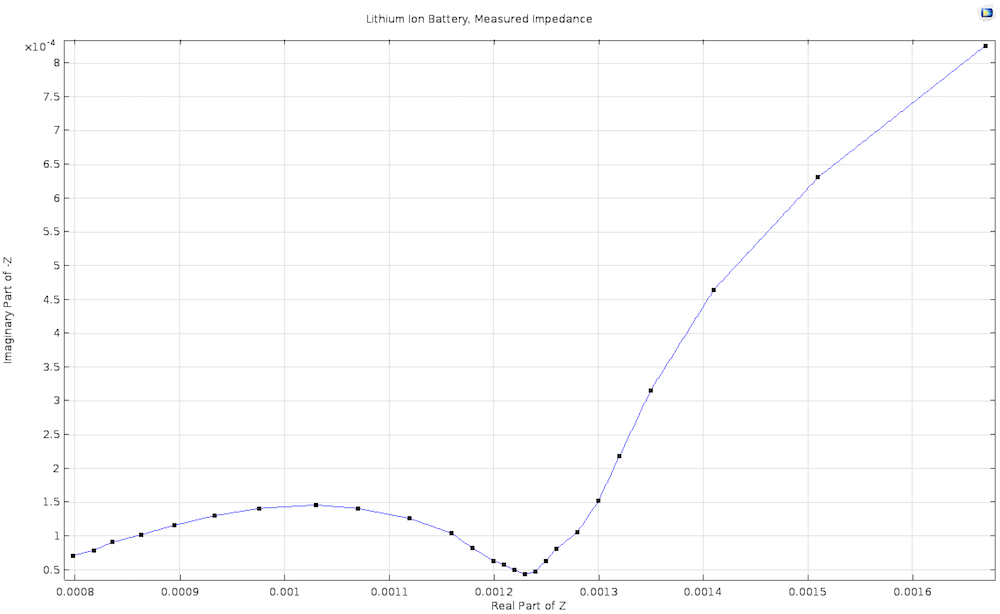
Double-layer capacitance is especially important in impedance spectroscopy, where the voltage is varied rapidly at high frequencies. Together with the finite electrode reaction rate and a finite rate of mass transport, it is a key factor in the characteristic “semicircle with a tail” shape of the Nyquist plot for many electrochemical systems.

An experimentally measured Nyquist plot for a lithium-ion battery, derived from our Lithium-Ion Battery Impedance demo app.
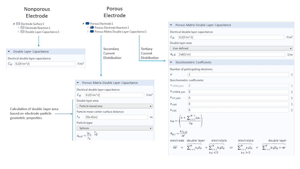
When defining an electrode surface, we can add a Double Layer Capacitance subnode. This electrode feature always requires a surface capacitance per area (in F m-2), though certain circumstances may require additional inputs. For example, for a porous electrode, the Porous Matrix Double Layer Capacitance feature requires the input of a specific surface area to determine the true surface area of the electrode-electrolyte interface, where a double layer exists and at which capacitive charging occurs. You can also use the built-in tools to calculate the double layer area of a porous electrode based on the particle properties of spheres, cylinders, or flakes. In this case, there is no need to explicitly know the specific surface area of the electrode.

An overview of the settings for the Double Layer Capacitance feature. The differences between nonporous and porous electrodes are shown, as well as the possibility to calculate the double layer surface area from some fundamental geometric properties instead of adding this directly as input.
Addressing More Complex Circuit Setups
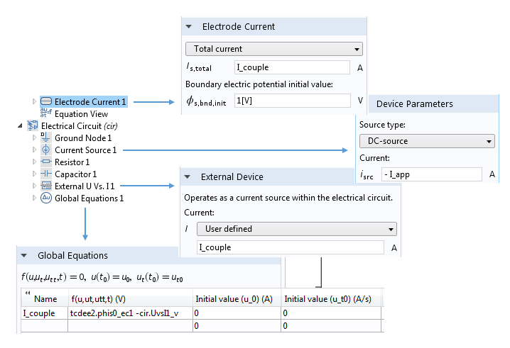
There may be occasional cases where it is desirable to connect an electrode to a more complex circuit in order to see how your electrochemical system couples with a complex driving circuit. Again, thanks to the flexibility of COMSOL Multiphysics, connecting any of the electrochemical physics interfaces to the Electrical Circuit interface is possible.

A typical setup for coupling a current-driven electrochemical system to a circuit representing instrumentation that supplies the current. Note how the currents in the Electrode Current and External Device settings are set to a common variable I_couple. The value of this variable is determined by constraining the voltages associated with these two nodes to be equal.
Advance Your Electrochemical Modeling by Accurately Describing Resistances and Capacitances
In today’s blog post, we have explained the approaches for describing electrochemical resistances and capacitances, while highlighting different cases in which each can be applied. We encourage you to use these tools and the knowledge that you have gained here to maximize the accuracy and usefulness of your electrochemical models.
Additional Resources for Modeling Electrochemical Systems in COMSOL Multiphysics®
- To learn more about including resistance and capacitance features in your electrochemical models, download the following tutorials:
- Watch this archived webinar for further details on simulating electrochemical systems in COMSOL Multiphysics


Comments (1)
Zahlen Chu
July 18, 2018Hi, Smith. Thanks for your sharing. It seems that Comsol provides us with several options to setup a electrode-electrolyte interface in terms of resistance and capacitance. From a perspective of electric circuit, the most complicated thing we can do is to add a resistance and a capacitor, making the interface a parallel RC circuit. What if we want it to be more complicated?
For example, I want to add an extra resistance in series with the double layer capacitor in terms of the electrode-electrolyte, if there any solution?
Thank you!