
Many elongated structures can be modeled effectively using 2D representations of their cross sections. A typical assumption is the plane strain approximation, which implies that all out-of-plane strain components are zero. This assumption is valid when the out-of-plane deformation is restrained; for example, when the ends of the structure are fixed. However, in many cases, the structure is free to expand in the out-of-plane direction. Let’s discuss how to model this case, which is sometimes called generalized plane strain.
Using Plane Strain, Plane Stress, and Generalized Plane Strain Conditions
Under plane strain conditions, no expansion in the out-of-plane direction is allowed. There are usually stresses in that direction caused by the coupling to the in-plane strain through a nonzero Poisson’s ratio. On the other hand, when a thin sheet is studied, the plane stress assumption is more useful. In this case, the material is free to contract or expand in the out-of-plane direction and the transverse stress is zero.
If the structure is long in the transverse direction when compared with its in-plane size, but is still not restrained in the transverse direction, then neither of these assumptions is good. This is where a generalized plane strain condition becomes useful.
About the Generalized Plane Strain State Formulation
A possible generalization of the plane strain formulation is to assume that the strains are independent of the out-of-plane coordinate. In the COMSOL Multiphysics® software, this generalization can be implemented using a 2D geometry of the cross section and the Solid Mechanics interface, in which the plane strain formulation is a default option.
The strain tensor components are assumed to be functions of only the in-plane coordinates x and y (and possibly time):
(1)
Under the small-strain assumption, the strain tensor components are related to the displacement field as:
(2)
The above equations have the following 3D solution:
(3)
{u\left( {x,y} \right) – \frac{{a{z^2}}}{2}} \\
\\
{v\left( {x,y} \right) – \frac{{b{z^2}}}{2}} \\
\\
{\left( {ax + by + c} \right)z} \\
\end{array}} \right]
where a, b, and c are constant coefficients.
The corresponding out-of-plane strains are:
(4)
{\varepsilon _{zz}} = ax + by + c \\
{\varepsilon _{xz}} = {\varepsilon _{yz}} = 0 \\
\end{array}\]
This strain state differs from the standard plane strain assumption only by the fact that the normal out-of-plane strain is nonzero and can vary linearly over the cross section. At the cross section z = 0, the deformation is in-plane and fully characterized by the in-plane displacement components u(x,y) and v(x,y).
The coefficients a, b, and c in the expression for the normal out-of-plane strain can be introduced as extra degrees of freedom (DOF) that are constant throughout the model (global variables). The extra strain contribution can be incorporated using the External Strain feature available in the Solid Mechanics interface.
A generalized strain formulation is important is when analyzing stress-optical effects, such as birefringence in waveguides composed of several layers of different materials (e.g., silicon-on-insulator waveguides). This stress-optical effects tutorial model shows such a case.
Example of Using the Generalized Plane Strain Formulation
To illustrate the efficiency of this approach, let’s consider a simple beam-like structure composed of two layers with square cross sections of 1 cm. The layers are made of materials with significantly different elastic and thermal properties: aluminum and nylon. The data is taken from the built-in Material Library in COMSOL Multiphysics. The length in the out-of-plane z direction is L = 20 cm. The structure is assumed to be manufactured at an elevated temperature. Due to the mismatch in the thermal expansion properties of the materials, a residual thermal stress builds up in the structure when it has cooled down to the operating temperature. This makes the structure bend slightly in the out-of-plane direction.
The following figure shows plots of the total displacement together with the deformation for a full 3D model and a 2D generalized plane strain condition:
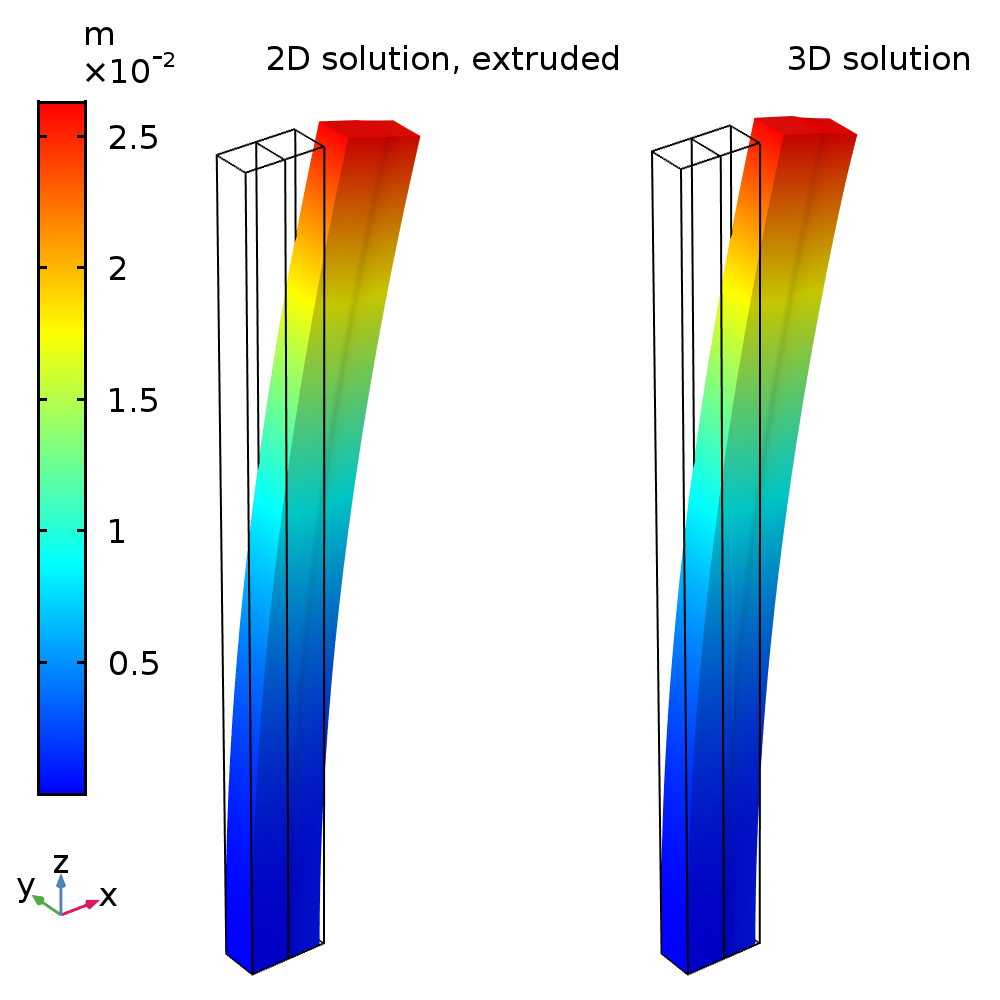
The 2D solution computed for u(x,y) and v(x,y) within the cross section has been extruded in the out-of-plane z direction using the analytical solution for the corresponding 3D displacement field given above.
The 3D solution requires around 32,000 DOF, while the 2D solution only needs around 250 DOF.
The following plots show the variation of the out-of-plane strain and stress along one of the edges.
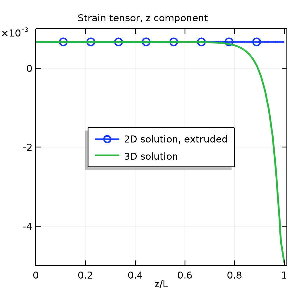
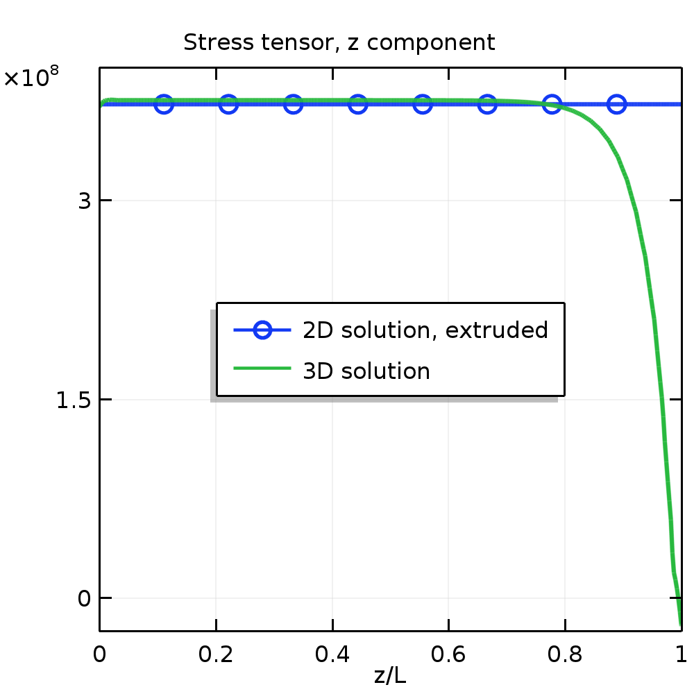
Strain (left) and stress (right) along the z-axis.
Around 80% of the true 3D structure has stress and strain fields similar to those predicted by the generalized plane strain theory. Only near the free ends, where the stress tends toward zero, does the strain field start to deviate from the linear distribution within the cross section.
Implementing the Generalized Plane Strain Condition in COMSOL Multiphysics®
One way to incorporate the changes needed for the generalized plane strain approximation is to start with a 2D component and the Solid Mechanics interface and then add the following nodes in the Model Builder tree:
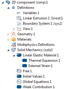
The Model Builder tree, showing the nodes needed to implement a generalized plane strain condition.
In addition to the standard settings for a 2D problem, you must perform the following steps. First, in the Global Equations node, add the a, b, and c coefficients as DOF. Note that you do not set up any equations for those variables here. Thus, all input fields other than the variable names are kept at their default values.
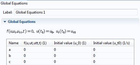
The Global Equations node, showing the a, b, and c coefficients.
In the Variables node, define the out-of-plane normal strain component eZ in terms of a, b, and c.
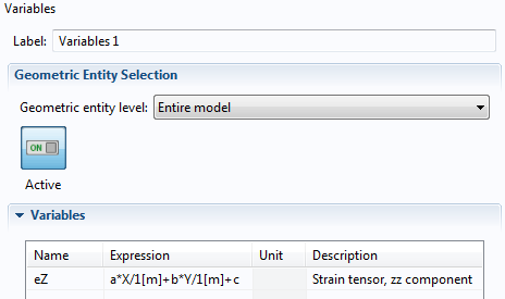
The Variables node, showing the expression for the variable eZ.
Next, incorporate the extra strain component into the stress-strain relation in the External Strain node. Note that any expression you enter in this node is subtracted from the total strains before the elastic stresses are computed from strains using Hooke’s law. Usually, this node can be used to incorporate inelastic effects; for example, strains caused by various electromechanical multiphysics effects. Here, we use it simply as a mechanism to inject an extra strain component that is zero by default in the plane strain formulation.
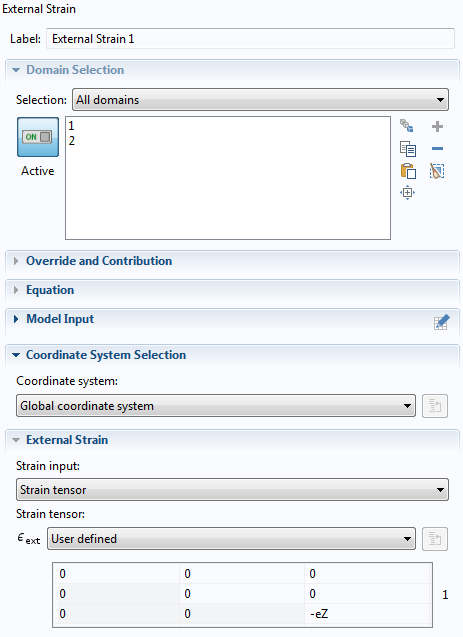
The External Strain node, showing the extra strain component.
Lastly, in the Weak Contribution node, include the extra virtual work done by the out-of-plane stress. This sets up equations (in the weak form) to determine a, b, and c. Here, solid.d is the thickness in the z direction, as defined in the Solid Mechanics interface.
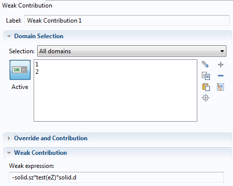
The Weak Contribution node, showing the weak expression.
Alternative Implementation
You can also skip the third and fourth steps above and insert the strain variable eZ directly into the equations of the Linear Elastic Material node. To do this, make sure Equation View is enabled.
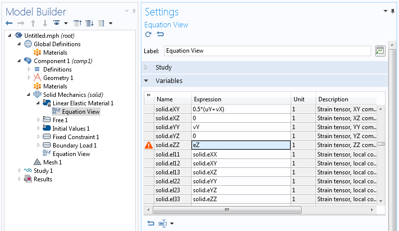
The settings for Equation View.
This way, the new strain in the z direction is directly part of the material model and goes into the weak expression that is already generated in the Linear Elastic Material node.
Concluding Remarks
We have shown how to use the functionality available in COMSOL Multiphysics to model elongated structures that are free to extend in the out-of-plane direction. The use of the 2D generalized plane strain approximation allows us to reduce the computation effort significantly while reproducing the possible out-of-plane bending of the structure — a 3D effect that can be important in applications such as piezoelectric devices and optical waveguides. It is also possible to incorporate out-of-plane shearing of the structure, which can be important in some piezoelectric applications.
Further Resources
- Learn more about structural mechanics modeling on the COMSOL Blog:


Comments (4)
Xiangnan Pang
July 26, 2017Good morning, this is a good article to illustrate the extension of Solid Mechanics Module. Actually I have been tried to using the PDE module (general form) to simulate the general plane strain about half years ago and I was not sure my model is correct or not. Now it shows another method in Solid Mechanics Module, I should compare it with my PDE module. Thanks.
Giho Jeong
September 4, 2017Please show me how to set the boundary conditions for multi-layer warpage problem unduced by thermal expansion. Because the model doesn’t have any axes of symmetry, it is important to assign the right BC’s
K g v kalyan Kumar
July 24, 2020What is the expression that can be used for true strain?
Blake Hendrix
December 1, 2022Doesn’t seem to work. A project file would be useful.