The beam envelopes method within the Wave Optics Module is a great feature for modeling photonic waveguiding structures. You can quickly set up models that compute the guided modes of a waveguide and how light propagating along the waveguide will be affected by, for example, anisotropies in the refractive indices of the materials. For devices with multiple supported waveguide modes and identical waveguide cross sections, there are some efficient modeling techniques to use. Let’s learn about such a situation.
Background on Optical Waveguides
In the field of photonics, many strategies exist for guiding light. The dielectric slab waveguide is always a good starting point, especially as a “textbook” example. More practically speaking, fiber optics, such as step-index fibers, dominate today’s communications infrastructure. For an overview of waveguiding and the field of photonics, see this previous blog post.

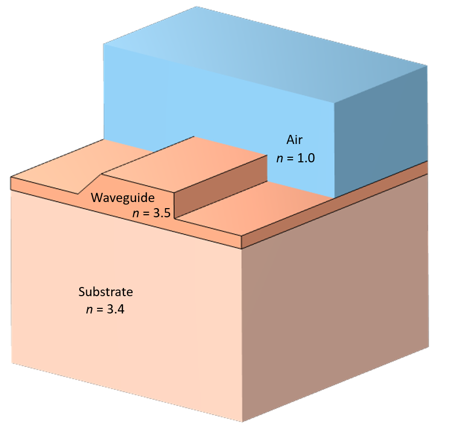
Schematic of an optical rib waveguide (not to scale).
What we will consider here is a rib waveguide, as pictured in the cross section above. This waveguide supports multiple modes that have quite similar effective indices, but where the electric fields are pointing in different directions. Suppose now that a section of the substrate of this waveguide has an anisotropic refractive index. As we have already discussed, such a waveguide will support yet another set of different modes.
Here, we will show how to model such a waveguide in 3D and how the polarization of light guided along the waveguide will rotate.
Computing the Supported Modes
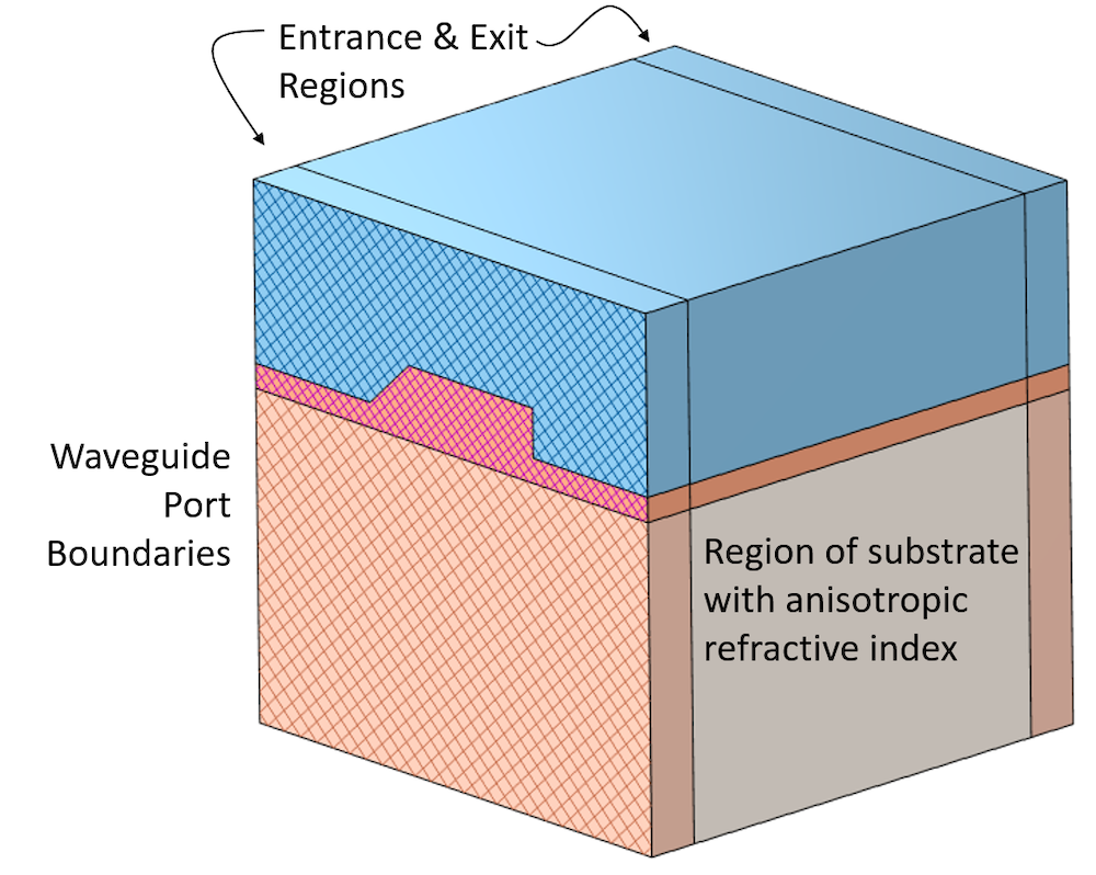
We will begin with a 3D geometry, as pictured below, of a straight waveguide, but subdivided into three sections. There will be an entrance region and an exit region. In these, we will assume that the refractive indices in all domains are isotropic. In the middle region, we will introduce an anisotropy in the refractive index of the substrate. This anisotropy might arise due to unwanted stresses in the substrate, or they may be purposefully introduced. We do want to introduce some kind of variation along the length of the structure, though, as otherwise, you could just model the case in 2D.

Schematic of the computational model (not to scale).
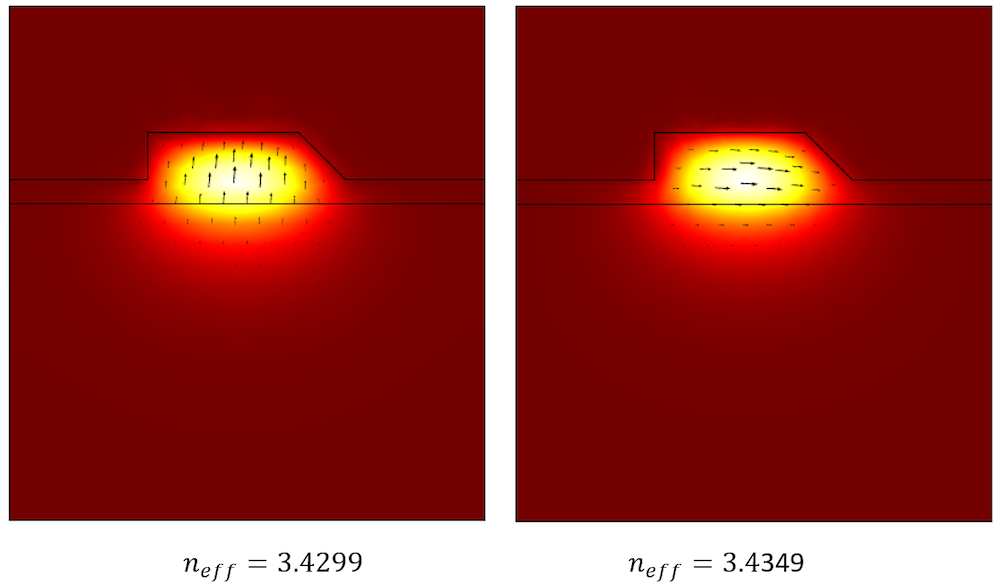
First, we will compute all of the waveguide modes of interest. We will concern ourselves only with the first two modes of a 1550 nm wavelength light. We can use a combination of the Numeric Port boundary condition and the Boundary Mode Analysis study to do so; the results of which are shown below. Note from the plot how the electric field extends fairly far into the substrate. We will use these two modes in the next part of our analysis, the 3D modeling, to both excite the structure and monitor transmission through it. We will inject one of these modes with the electric field pointing upward, and as this mode propagates through the anisotropic region, we want to find out if and by how much this mode gets converted into the other mode at the exit. To do so, we will need to reuse and copy these solutions.

Visualization of the electric fields of the first two waveguide modes.
Modeling Polarization Rotation in the Full 3D Waveguide
Once all of the Numeric Port modes of interest have been computed and mapped to their respective User-Defined Port boundary conditions, we are ready to finish up the 3D model. The Electromagnetic Waves, Beam Envelopes interface takes the average wave vectors of the two modes of interest as the input, and here, we use the Unidirectional formulation. This is appropriate in our case because we will assume that light is solely propagating from the entrance to the exit, but that there is negligible reflection back toward the entrance.
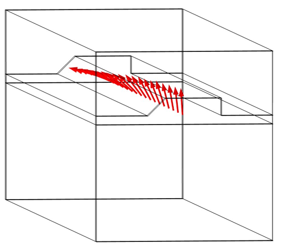
Once solved, we can plot the absolute value of the electric field components along a line down the center of the waveguide. We can also evaluate the transmission into the two ports at the exit, which gives us a measure of how much the fields rotated through the device. In the entrance region, with isotropic properties, only the injected mode exists. Once this mode propagates into the region with the anisotropic substrate, which supports a different set of modes, there will be a gradual conversion into these modes that causes the fields to rotate. These modes also have slightly different propagation constants, which will lead to a beating phenomena along the length that will become more evident if we model an even longer section. At the exit region, though, all of the material properties are isotropic and only the original two previously computed modes can exist.

Results showing the rotation of the electric field along the length of the waveguide.
Closing Remarks
The model is available for download via the following article: “Copying and Reusing Boundary Mode Analysis Results“. This model is differentiated from other examples, such as the directional coupler, in that we are computing the boundary modes via a separate study and using operators to copy the numerically computed modes. For models with multiple ports, such as interferometers and resonators, this technique can be quite efficient.


Comments (0)