
Bearings, specifically rolling element bearings, are some of the most commonly used industrial components. These bearings are found in gearboxes, conveyors, motors, and rolling mills due to the low friction and low starting torque compared to hydrodynamic bearings. They can also handle changes in speed, temperature, and loads. In this blog post, we will look at different bearing types and demonstrate how to model a rotor system supported on roller bearings using the COMSOL Multiphysics® software.
What Is a Rolling Element Bearing?
Rolling element bearings typically consist of four parts:
- Inner race
- Outer race
- Rolling elements
- Cage
The inner race is connected to the shaft and the outer race is connected to the bearing pedestal. Multiple rolling elements are inserted between the inner and outer races, which enables them to slide relative to each other with the help of the rolling motion of the elements. The cage keeps the rolling elements separated from each other.
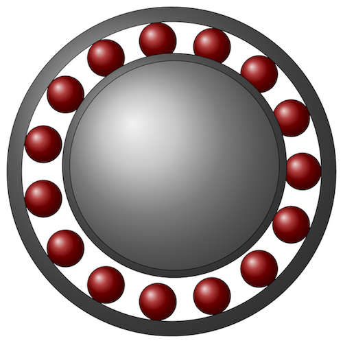
Front view of a typical rolling element bearing with an off-centered shaft.
A rolling element bearing helps support loads while permitting the constrained motion of the inner race relative to the outer race. Bearing models are available in COMSOL Multiphysics for the following bearing types:
- Deep groove ball
- Angular contact ball
- Self-aligning ball
- Cylindrical roller
- Spherical roller
- Tapered roller
There is a point contact between the rollers and the races in deep groove ball bearings, angular contact ball bearings, self-aligning ball bearings, and spherical roller bearings. However, in cylindrical and tapered roller bearings, there is a line contact. Generally, line contact bearings have a larger load-carrying capacity than point contact bearings. To increase the load-carrying capacity of a bearing, multiple rows of rolling elements are sometimes used instead of a single row.
The bearing geometry plays an important role in deciding its application area. For example, deep groove ball and cylindrical roller bearings cannot support axial loads, whereas angular contact ball bearings and tapered roller bearings can withstand significant axial loads. Self-aligning ball bearings are another special example, where the shafts can tilt within the bearings, thus making them suitable for cases of misaligned mounting. Common application areas for the different bearing types are shown below:
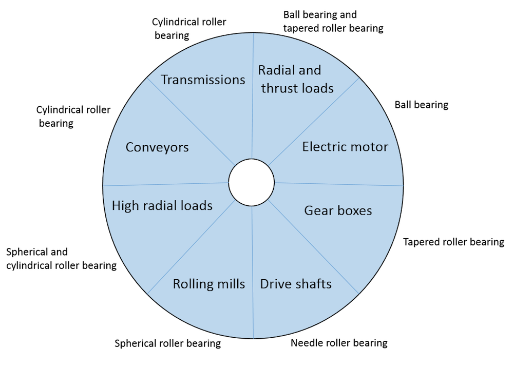
Application areas of the different types of bearings.
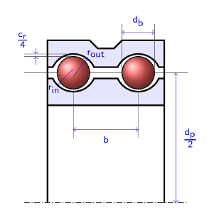
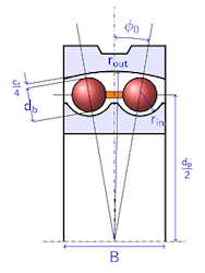
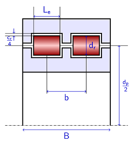
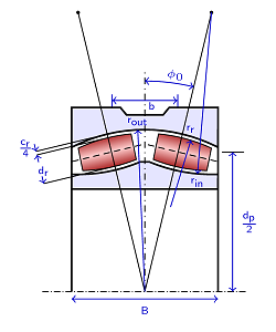
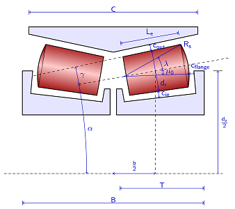
Roller bearings in COMSOL Multiphysics are the abstract models for the contact between the rollers and races based on the Hertz contact theory. Therefore, you need to input the geometric parameters to account for the specific characteristics of the bearings. The images below show the geometric parameters of the different types of bearings with two rows of rollers.
Sketches of the deep groove ball bearing (left), angular contact ball bearing (center), and self-aligning ball bearing (right).
Sketches of the cylindrical roller bearing (left), spherical roller bearing (center), and tapered roller bearing (right).
In addition to the geometric parameters, material parameters of the rollers and the races play an important role in the bearing characteristics. A nonlinear Hertzian contact law is used to determine the deformation of the rollers and the transmitted force vector from the inner race to the outer race.
The clearance between the rollers and races is a very important parameter that strongly affects the rotor vibration. A smaller clearance reduces the high-frequency vibration but increases the torque required to operate the bearings. A very large clearance, however, can excite the high-frequency vibrations in the rotor with the large forces and moments acting on the bearing foundation, which is best avoided.
Modeling a Rotor System with a Roller Bearing
Let’s take a look at the effect of the roller bearing clearance on the rotor vibration by considering the rotor assembly of a blower in a continuous casting machine. Continuous casting is a process through which molten metal is solidified into billets. The blower in the casting machine accelerates the cooling of the molten metal stream, which enters into the mold by blowing cold air on the mold.
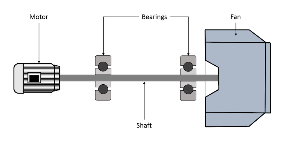
Schematic of the rotor assembly.
The blower assembly consists of a driving motor connected to a shaft, which is connected to the blower fan. The shaft is supported by two roller bearings placed between the motor and blower. Thus, the blower fan is overhung on the bearing support.
Axial rotation of the rotor in combination with the bending of the shaft due to overhung weight gives rise to the whirling motion in the rotor. Also, due to the contact between the rollers and the races, high-frequency vibrations can be induced in the rotor. A time-dependent analysis is performed to capture this vibration in the shaft for different bearing clearances.
The shaft is modeled using the Beam Rotor interface in COMSOL Multiphysics, which uses beam elements based on Timoshenko theory. The shaft at the motor end is considered to be fixed and is modeled using the Journal Bearing feature, and the fan is modeled using the Disk feature using its mass and moment of inertia.
A Radial Roller Bearing feature is used to model the bearing, which requires the geometric and material properties of the bearing components. The rotor rotates at 2000 rpm and the whole system is subjected to gravity load. The effect of the roller bearing clearance on the shaft vibration is analyzed by considering three different clearances values: C = 1e-5 m, 1e-4 m, and 1e-3 m.

Physics features for modeling the rotor system.
Analyzing the Simulation Results
A simulation is performed for 1 second with a time step of 1e-3 second. The orbit of the shaft at the fan end for different clearances is shown in the figure below:
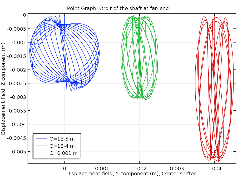
Orbits of the shaft at the fan end for different bearing clearances (center-shifted for C = 1e-4 m and C = 0.001 m).
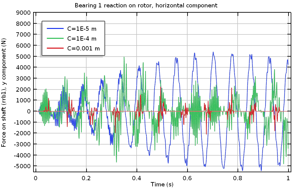
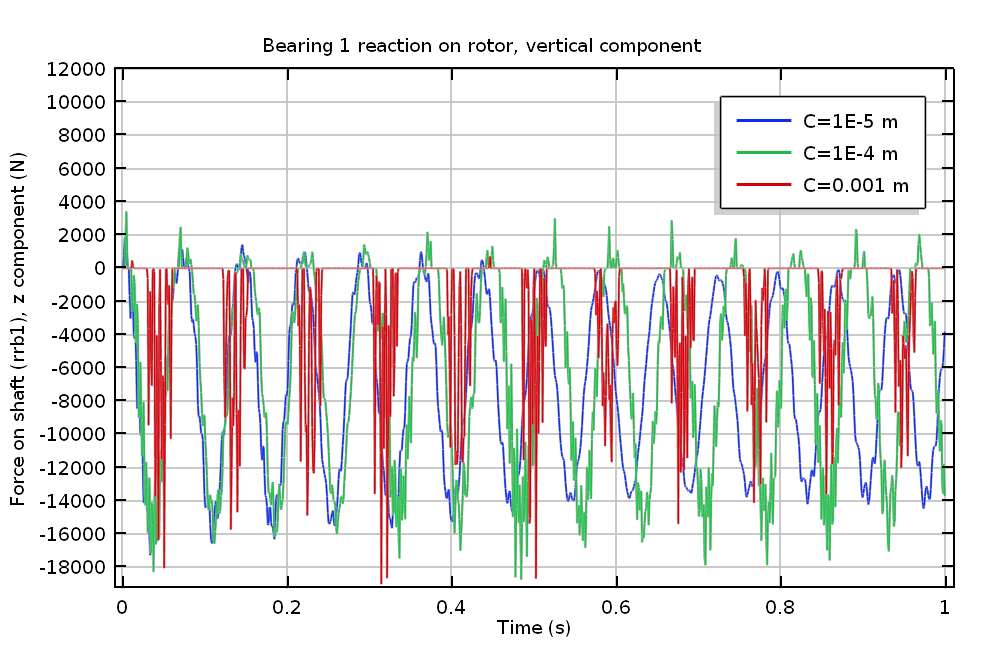
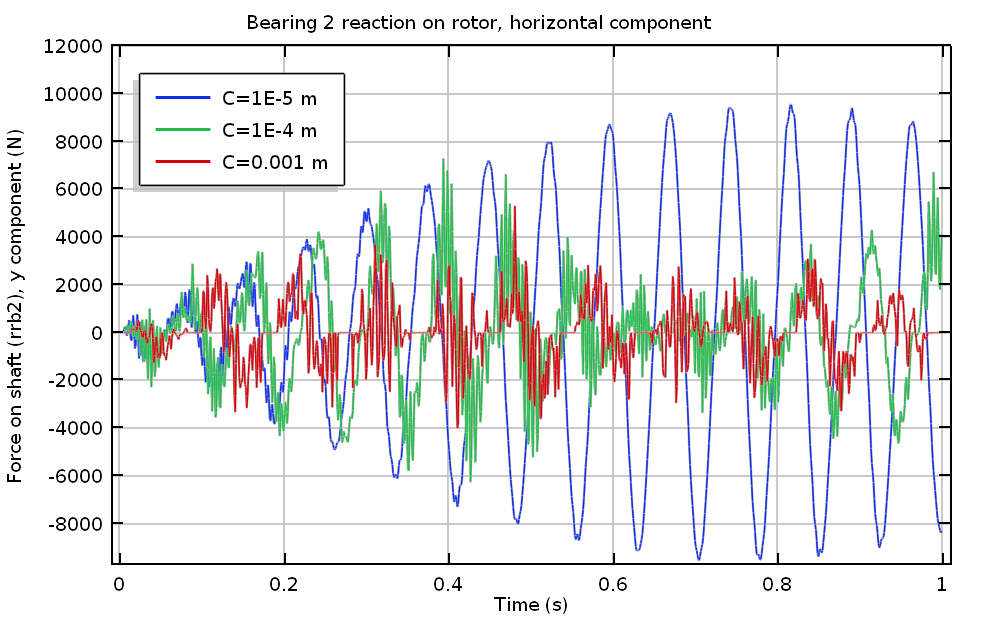
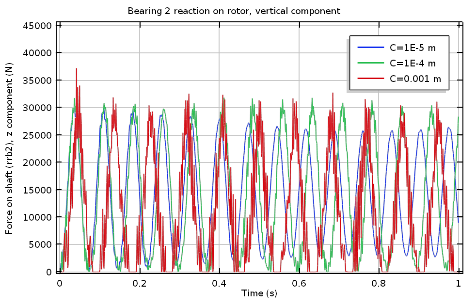
From the orbits, it is clear that for a smaller clearance, the vertical motion is smaller than it is for the larger clearances. However, the horizontal motion of the shaft for the small bearing clearance is larger than it is for larger bearing clearances. Therefore, at smaller clearances, the contact between the races and rollers is maintained at all times. When the clearance increases, contact can become intermittent, causing the impact between the races and rollers. Bearing forces at the different clearances shown below confirm this behavior.
The vertical reaction of Bearing 2 (closer to the fan) is upward, supporting the overhung weight of the fan. However, the vertical reaction of Bearing 1 is downward the entire time because of the bending of the shaft due to the overhung weight. It is also clear that the horizontal reaction of the bearings is very intermittent at the large clearances, indicating seldom contact between the rollers and the races in the horizontal direction.
Horizontal reaction of Bearing 1 (left) and vertical reaction of Bearing 1 (right).
Horizontal reaction of Bearing 2 (left) and vertical reaction of Bearing 2 (right).
The intermittent force may induce high-frequency vibration in the rotor. A frequency spectrum of the shaft’s horizontal motion in the bearing closer to the motor shows the presence of high-frequency vibration at large clearances. As the clearance decreases, the high-frequency vibrations are less significant.
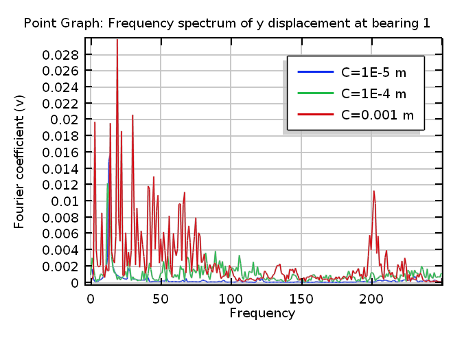
Frequency spectrum of the horizontal motion of the shaft at Bearing 1.
During the rotor’s operation, due to wear, the bearing clearance may increase over a period of time. Because of this, the vibration response of the rotor will have high-frequency content too. If the measured rotor response has some high-frequency content, it could be an indicator that the bearings are worn out and should be replaced.
Next Steps
Learn more about using the COMSOL® software for rotordynamics analysis by clicking the button below.
- Check out these additional blog posts on modeling rotors and rotating machines:
- Watch an archived webinar on how to use the Rotordynamics Module





Comments (3)
Valery Anpilov
January 10, 2019very useful information for those who began to explore the possibilities of this module
Prashant
January 14, 2019 COMSOL EmployeeThank you Valery!
MG
May 22, 2019Dear Prashant Srivastava,
Thanks for such an comprehensive piece of article for bearing design in COMSOL. I am more interested in COMSOL .mph file for time/frequency domain analysis. Can you help me in providing some example file ?
Thanks and Regards,