
Whenever light is incident on a dielectric material, like glass, part of the light is transmitted while another part is reflected. Sometimes, we add a metal coating, such as gold, which alters the transmittance and reflectance as well as leads to some absorption of light. The dielectric surface and the metal coating also often have some random variations in height and thickness. In this blog post, we will introduce and develop a computational model for this situation.
Starting Simple: An Optically Flat Surface
Before we get to the rough surface, let’s start with something simple: a thin uniform layer of gold coating on top of optically flat glass, as shown in the image below. Such a model exhibits negligible structural variation in the plane of glass. In addition, it can be modeled quite simply in the COMSOL Multiphysics® software by considering a small two-dimensional unit cell that has a width much smaller than the wavelength.
This computational model is based on the Fresnel equation example, one of the verification models in the Application Gallery, but is modified to include a layer of gold with a wavelength-dependent refractive index. This type of index requires that we manually adjust the mesh size based on the minimum wavelength in each material as well as the skin depth, as described in a previous blog post.
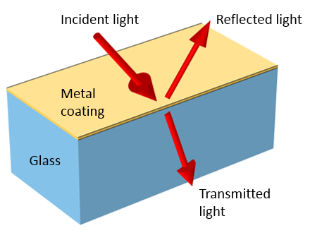
Light incident on a metal coating on top of a glass substrate is reflected, transmitted, and absorbed.
The model includes Floquet periodic boundary conditions on the left and right sides of the modeling domain and a Port boundary condition at the top and bottom. The Port boundary condition at the top launches a plane wave at a specified angle of incidence and computes the reflected light, while the one at the bottom calculates the transmitted light. We can integrate the losses within the metal layer to compute the absorbance within the gold layer.
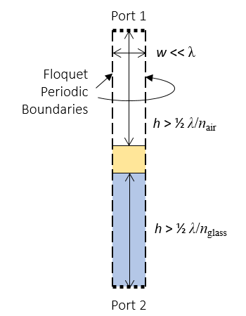
The computational model that calculates the optical properties of a metal film on glass.
If we are interested in computing incident light at off-normal incident angles, then we also have to concern ourselves with the height of the modeling domain — the distance between the material interfaces and the Port boundary conditions. This distance must be large enough such that any evanescent field drops off to approximately zero within the modeling domain.
The reason for this has to do with the Port boundary conditions, which can only consider the propagating component of the electromagnetic field. Any evanescent component of the field that reaches the Port boundary condition is artificially reflected, so we must place the port boundary far enough away from the material interfaces. In the most general cases, it is difficult to determine how far the evanescent field extends. A simple rule of thumb is to place the Port boundary conditions at least half a wavelength away from the material interfaces and to check if making the domain larger alters the results.
The sample results below show the transmitted, reflected, and absorbed light as well as their total — which should always add up to one. If these do not add up to one, then we must carefully check our model setup.
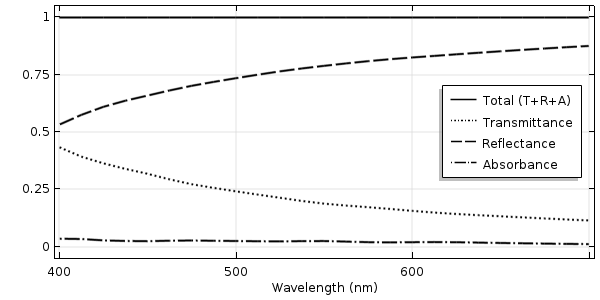
The transmittance, reflectance, and absorbance of light normally incident on a flat glass surface with a metal coating as a function of wavelength.
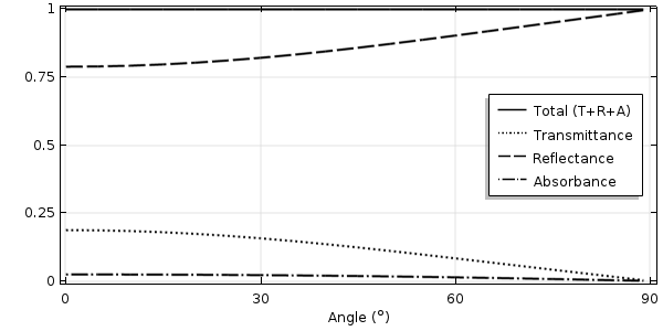
The transmittance, reflectance, and absorbance of 550-nm light at various angles of incidence.
Adding Complexity: A Surface with Periodic Variations
Let’s now make things a little bit more complicated and introduce a periodic structural variation: a sinusoidal ripple. Clearly, we now need to consider a larger unit cell that considers a single ripple.
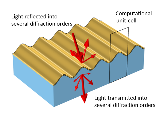
A surface with periodic variations reflects and transmits light into several different diffraction orders.
We can still apply the same domain properties and all of the same boundary conditions. However, if spacing is large enough, then we can have higher-order diffraction. In other words, light can be reflected and transmitted into several different directions. To properly compute the reflection and transmission, we need to add several diffraction order ports. The software computes the appropriate number of ports based on the domain width, material properties, and specified incident angle. If we are studying a range of incident angles, we must make sure to compute all of the diffraction orders present at the limits of the angular sweep.
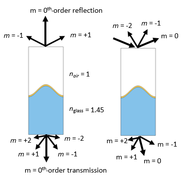
There can be multiple diffraction orders present, depending on the ratio of wavelength to domain width, refractive index, and incident angles.
The conditions under which higher-order diffraction appears and the appropriate modeling procedure is presented in depth in the example of a plasmonic wire grating, so let’s not go into it at length here. In short, the wider the computational domain relative to the wavelengths in the materials above and below, the more diffraction orders can be present (the number of diffraction orders varies with the incident angle). The results shown below plot the total transmittance and reflectance; i.e., all of the light reflected into the different diffraction orders is added up, as is all of the transmitted light.
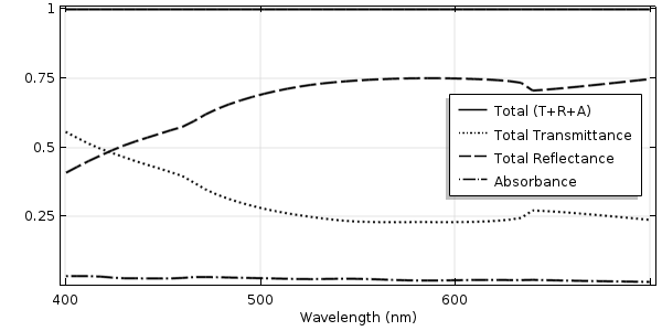
The transmittance, reflectance, and absorbance of light normally incident on a rippled glass surface with a metal coating.
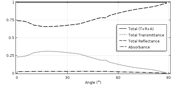
The transmittance, reflectance, and absorbance of 550-nm light at various angles of incidence.
Solving a More Difficult Case: A Surface with Random Roughness
Let’s now move on to the most computationally difficult case: a surface with many random variations in the surface height. To model the randomness, we must model several different domains of increasing widths and different subsets of the rough profile. As the domain width increases — and as different subsets of the surface are sampled — the average behavior computed from these different models converges. That is, we generate a set of statistics by sampling the rough surface. Rather than going into detail on how to calculate these statistics, let’s focus on how to model one domain that approximates a rough surface by defining the height variation as the sum of different sinusoids with random height and phase, as described here.
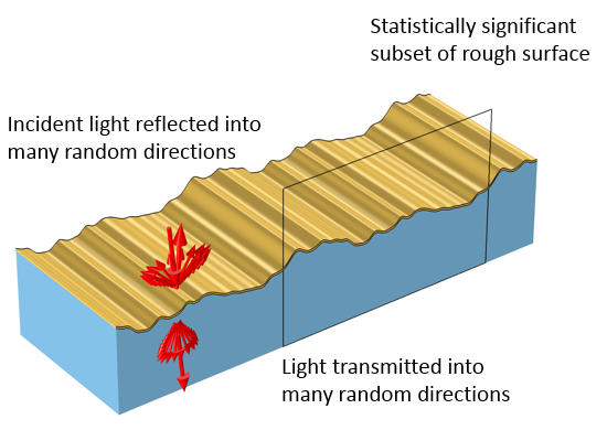
A rough surface with random variations reflects and transmits light in random directions. The computational model must sample a statistically significant subset of the roughness profile.
Our computational domain must now be very wide, many times longer than the wavelength. As we still want to model a plane wave incident at various angles on the structure, we use the Floquet periodic boundary conditions, which require that we have an identical mesh on the periodic boundaries. Practically speaking, this means that we may need to slightly alter the geometry of our domain to ensure that the boundaries on the left and right side are identical. If we do use a sum of sine functions, as described here, then the profile will automatically be periodic.
We still want to launch the wave with a Port boundary condition. However, it is no longer practical to use diffraction order ports to monitor the reflected and transmitted light, as this can result in hundreds (or thousands) of diffraction orders. Furthermore, since this model represents a statistical sampling, the relative fraction of light scattered into these different orders is not of interest; we’re only interested in the sum of the total reflected and transmitted light. That is, this modeling approach computes the total integrated scatter plus the specular reflection and transmission of the surface.
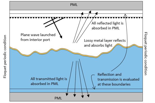
The computational domain for a model of a rough surface. Light is launched from the interior port toward the material interface. Light reflected back toward this port passes though it and is absorbed in the PML, as is the transmitted light. Two additional boundaries are introduced to monitor the total reflectance and transmittance.
Thus, we introduce an alternative modeling strategy that does not use ports to compute reflection and transmission. Instead, we use a perfectly matched layer (PML) above and below to absorb all reflected and transmitted light as well as probes to compute reflection and transmission. PMLs absorb any fields incident upon them, as described in this blog post on using PMLs for wave electromagnetics problems.
The PML absorbs both propagating and evanescent components of the field, but we only want it to absorb the propagating component. Thus, we again need to ensure that we place the PMLs far enough away from the material interfaces. We use the same rule of thumb as before, placing the PML at least half a wavelength away from the material interfaces.
As we approach grazing angles of incidence, even the PML domain does not, by default, absorb all of the light. At nearly grazing angles, the effective wavelength in the absorbing direction is very long, and we need to modify the default wavelength in the PML settings (shown below). This change to the settings is only necessary if we are interested in angles of incidence greater than ~75°.
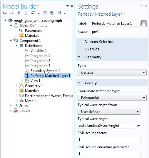
The PML settings modified to account for grazing angles of incidence.
Since our domain is now bounded by PMLs above and below, the port that launches the wave must now be placed within the modeling domain. To do this, we use the Slit Condition option to define an interior port that is backed by a domain. This means that the port now launches a wave in one direction, emanating from this interior boundary. Any light reflected back toward the boundary passes through unimpeded and then gets absorbed by the PML.
Although this is a good way to launch the wave, we will no longer use the Port boundary condition to compute how much light is reflected, since we would have to add hundreds of diffraction ports, and similarly, we’d need hundreds of ports to compute the total transmittance.
To monitor the total transmitted and reflected light, we instead introduce two additional interior boundaries to the model, placed just in front of the PML domains (shown in the schematic above). At these two boundaries, we integrate the power flux in the upward and downward directions, normalized by the incident power, which gives us the total reflectance and transmittance. To more accurately determine the integral of the power flux at these boundaries, we also introduce a boundary layer mesh composed of a single layer of elements much smaller than the wavelength.
On the incident side, we place this monitoring boundary above the interior port. The launching port introduces a plane wave propagating toward the material interface. The light reflected at the interface passes through this interior port, then moves through the boundary at which we monitor reflectance, and is absorbed in the PML.
The plots below show sample results of the transmittance, reflectance, and absorbance. They are notably different from the smooth surface and periodically varying surface results. Note that the sweep over the angle of incidence terminates at 85° off normal. Of course these plots will look slightly different for each different random geometry case that we run.
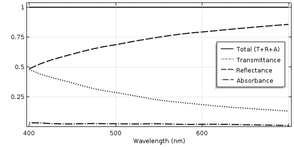
The transmittance, reflectance, and absorbance of light normally incident on a rough glass surface.
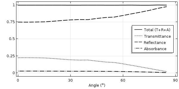
The transmittance, reflectance, and absorbance of 550-nm light at angles of incidence up to 85° off normal.
Concluding Thoughts on Calculating the Optical Properties of Rough Surfaces
Here, we have introduced a modeling approach that is appropriate for computing the optical transmission and reflection from a rough surface. This method contrasts with the approach for modeling a uniform optically flat surface as well as the one for modeling surfaces with periodic variations. The modeling method for rough surfaces can also be used for the modeling of periodic structures that have a very long period, such as when the scattering into different diffraction orders is not of interest.
Modeling truly random surfaces does require some care, as the geometry needs to be altered to ensure that it is periodic. Furthermore, the domain size and number of different random geometries studied must be large enough to give statistically meaningful results. Since this requires solving many different variations of the same model and postprocessing the results, it is helpful to use the Application Builder, LiveLink™ for MATLAB®, or LiveLink™ for Excel® in our modeling workflow.
Further Resources
- See how to create a rough surface as a sum of sine functions
- See how to create a random geometry using methods
- Check out other blog posts related to simulating wave optics:
MATLAB is a registered trademark of The MathWorks, Inc. Microsoft and Excel are either registered trademarks or trademarks of Microsoft Corporation in the United States and/or other countries.


Comments (19)
Xu Xu
June 6, 2017Hi Walter,
Can you explain a bit more about the the effective wavelength in the absorbing direction with relate to the PML.
And why the angle in the denominator is incidence angle,not scattered angle.
best,
Xu
Wajid Ali
June 7, 2017Hello Sir,
My question is slightly irrelevant but I am facing great problem that how to apply constant magnetic field of 1.5 T along with the direction of propagation of light while finding the absorption cross section of gold nano sphere .
Please help me
Thanks
Regards
Ali
wakhanqau@yahoo.com
Walter Frei
June 7, 2017 COMSOL EmployeeHello Xu,
There is indeed scattering into many angles. The approach shown here assumes an “average” angle that turns out to be quite good in practice at all but nearly grazing incident angles. Although you are theoretically correct that we should adjust the angle, it turns out to not make a very big difference. In fact, you could even just use the default PML settings and get reasonably similar results up to about 65° incident angles.
Emine Kaya-Cekin
October 30, 2017Hello Walter,
Is there any feature that is new to the version 5.3 in these models? Models are available in the application gallery but they are all built in 5.3. (I cannot open them with 5.2a) Could you at least provide the pdf form of the application files for these models?
Thanks!
Caty Fairclough
November 3, 2017Hi Emine,
Thanks for your comment and interest in this blog post! For your question, we would suggest contacting your sales representative to get back on subscription.
Thank you!
mona aghaee
January 29, 2018Hi,
I have problem modeling radiation heat transfer in a slab. A constant radiation hits an slab and part of that is transferred through the slab, part is absorbed within the slab and part is reflected. How should I model this? I already know the absorptance, reflectance and transmittance. Please advise.
Thanks
Mona
Kriti Agarwal
April 9, 2018Hi Walter,
I am trying to adapt this model for 3D simulations. Can you please advise me as to what changes should be made to the power flux calculation for the reflection and transmission computations?
Thanks,
Kriti
Caty Fairclough
April 26, 2018Hi Kriti,
Thanks for your comment.
For your question, I would suggest contacting our Support team.
Online Support Center: https://www.comsol.com/support
Email: support@comsol.com
Ahmad Khayyat Jafari
May 29, 2018Dear Walter,
Thanks for all of your blogs. I found them very useful.
I have a comment about this blog.
As we know, when we use PML we can only measure the reflection, transmission and absorption. In fact, there is no way to look at the different diffraction orders. Now, if it happens that we have non-zero loss of energy in one or more of diffraction orders, we don’t get one by adding reflectance, transmittance and absorbance. In this case, we have to consider the important diffraction orders (the ones which have energy loss). For instance, in my simulations, whenever I use PML, I can’t get one in some regions of the spectrum. But, when I take into account the contribution of important diffracted orders, I can get one. Also, the graphs are a bit better in the case of using Ports (when I use PML, parts of graphs have ripple whereas for the case of Port, there is no such ripples).
Joseph Gibbons
January 17, 2019Dear Walter,
Thank you for the blog post(s)!
Do you have a sort of step-by-step walkthrough guide for the three individual models (i.e., optically flat, periodic variations, and random roughness)? I am really keen to design this and modify for my own specific needs, accordingly.
Happy to discuss.
Kind regards,
Joseph.
Walter Frei
January 17, 2019 COMSOL EmployeeHello Joseph,
The files themselves should be available via the link above. We do not publish step-by-step instructions for all these files, good related starting points, with instructions, are:
https://www.comsol.com/model/fresnel-equations-wave-optics-14713
https://www.comsol.com/model/plasmonic-wire-grating-wave-optics-14705
Daniele Di Rosa
May 16, 2019Hello,
I’m a beginner with Comsol, and I tried to reproduce the simulation of the flat surface, following the tutorial of the Plasmonic Wire Grating. I have a doubt about the Port boundary conditions, in particular with the computation of the diffraction orders. If I understood well, the number of diffraction orders of the “transmission” Port 2 depends on the wavelength and the incidence angle of the input wave, and Comsol computes them automatically when I click on the “Compute Diffraction Orders” button. This works fine when I have a constant wavelength and a constant angle of incidence, but how does the software handle this calculation when I have to run a Parametric sweep study? I mean: if I let the incident angle sweep from 0 to 89 deg, does Comsol compute the number of diffraction orders each time (for each value of the incident angle)?
Thank you
Joseph Gibbons
June 27, 2019Dear Walter,
I managed to implement the above model, and adjust for my needs accordingly.
However, I’m encountering difficulties and would be appreciated if you could lend any advice or guidance. I am now trying to measure the optical properties of a rough surface into the far-infrared region – although my model does compute this, the results aren’t as expected.
Could this be caused by the refractive index of the material being constant (from the database)? And would implementing a variable for the dispersion formulae of the material perhaps be a solution?
Have modelled anything in the NIR or IR region using COMSOL? And if so, are there certain steps or modifications needed for the model?
Happy to discuss.
Kind regards,
Joseph.
Panos Koniavitis
July 3, 2019Hi there. I bumped onto this thread and I was wondering if I am able to modify or adjust the surface roughness of a surface. I am running a heatsink calculation and I would want to see how the surface roughness affects the thermal efficiency/resistance of the heat sink. Is there an option in COMSOL 5.4?
Thank you in advance.
Best regards,
Panos
Ajreen Qammar
November 19, 2019Hello sir,
i can use this type of model with some modifications to calculate the absorbance of other dielectric material?except metal.please reply
thanks
Panyiming Liu
May 17, 2021Hello Sir,
My question is why Airheight is defined as L_max in Model. Thank you~
Best,
Panyiming
Preetpal Singh
November 5, 2023Can i have the “Computing the Scattering of Light from a Rough Surface with a Metal Coating” mph file in 6.0 version or before as i can not execute the 6.1 version or the pdf file to learn to execute this method?
Can email it to my email id: preetpalsingh96@gmail.com.
Thanks, Preetpalsingh
Collins Kariuki
March 15, 2024How can I create a graph showing reflectance as a function of the angle of incidence? I’ve successfully plotted reflectance against wavelength, but I’m unsure how to approach plotting it against the angle of incidence.
Walter Frei
March 18, 2024 COMSOL EmployeeHello Collins,
The examples, available via the link above, demonstrate this. Additional examples, with instructions, are:
https://www.comsol.com/model/fresnel-equations-wave-optics-14713
https://www.comsol.com/model/plasmonic-wire-grating-wave-optics-14705