
Say you want to compute thermal expansion and stresses in an object. You provide the heat fluxes and temperature constraints on the boundaries, compute, and get a convergence error. Often, this result comes from a lack of displacement constraints. However, it is not trivial to provide constraints that do not induce artificial stresses. Today, we showcase the Rigid Motion Suppression feature in the COMSOL Multiphysics® software, which you can use to automatically figure out the constraints you need.
Kinematic Constraints in Structural Analyses
In a stationary or quasistatic structural analysis, we are looking for an equilibrium solution. Whereas the object is free to deform, it is not free to move or rotate as a rigid body. To this end, the reaction forces have to balance the applied forces. Reaction forces come from constraints on displacements and rotations. In 2D, we need to prevent two displacements and one rotation. In 3D, we have three displacements and three rotations to constrain.
If constraints are not provided, the out-of-balance forces want to move or rotate the object. This is inconsistent with the equilibrium assumption. As such, there are multiple solutions to the problem that differ from each other by a rigid body motion. The resulting stiffness matrix is singular and the stationary solver fails to converge.
Another way of looking at this problem is from the mathematical side. The equilibrium equations, which are elliptic partial differential equations, need sufficient Dirichlet boundary conditions to have unique solutions.
This is not a concern in dynamic analysis because of the presence of the inertial term. Unlike in a stationary analysis, where there should be no unbalanced forces, an unbalanced force in a dynamic analysis is free to cause accelerations. The equations here are hyperbolic and they do not need Dirichlet boundary conditions to be well posed. Note here that we are talking about dynamic analysis and not just a quasistatic time-dependent analysis where we ignore inertial contributions. The example we discuss in this blog post is a stationary analysis.
Failing to Converge: A Thermal Expansion Problem
Let’s consider an example where we want to study stresses in a layered plate made out of a substrate and coating with different coefficients of thermal expansion (CTE). The coating is deposited on the substrate at a temperature of 800°C when the layered plate is stress-free. We want to find the stress due to CTE mismatch if we lower the temperature to 150°C. In this example, since we know the final temperature everywhere, we do not need to solve a heat transfer problem. We can just add the Thermal Expansion attribute to the Linear Elastic Material node.
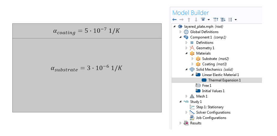
A thermal expansion simulation without sufficient displacement constraints fails to converge.
The substrate, which has a higher CTE, wants to contract more than the coating when cooled. But gluing them together forces them to have the same displacement at the common boundary. Thus, we expect tensile stresses in the substrate, compression in the coating, and overall bending of the structure. Yet, clicking Compute at this point only gives us a convergence error of the type “Failed to find a solution”, again, because the analysis doesn’t have a unique solution.
Achieving Convergence with “Brute Force”
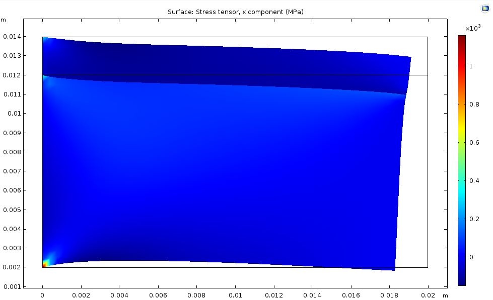
If we add fixed constraints on some of the faces, say, the left two, we will definitely prevent rigid body displacements or rotations. Alternatively, if we add symmetry conditions on the left and bottom faces, constraining normal displacements on nonparallel faces, we will also prevent rigid body motion. In either case, we get convergence. Here are the results for the normal stresses in the x direction plotted on a deformed configuration with exaggerated displacements.
Solutions with fixed constraints on the left vs. symmetry conditions on the right.
The above solutions have very different stress distributions as well as deformation patterns. At least one of the two solutions should be wrong. For example, if our problem is symmetric, we could use only a quarter of our simulation domain and the symmetry boundary condition. As a side benefit, exploiting symmetry cuts down on computation memory and time requirements. That is what we can do if we have a second coating layer of the same thickness at the bottom. If we are artificially forcing symmetry, we are going to get a converged, yet irrelevant solution.
If this layered plate was freely lying on a tabletop and did not have symmetry, both of the above boundary conditions would give us wrong solutions. Convergence is not enough: We want to converge to a physically correct solution. To this end, we want to provide constraints that stabilize the model without distorting the stress state.
Manual Approach to an Accurate Solution
If the problem has enough symmetries, it is preferable to use them, as discussed above. If that is not the case, we need to come up with displacement constraints that do not introduce artificial stresses. There are several options here. One alternative is to use the “3-2-1” approach:
- Select three noncollinear points that are well separated (for a 3D model)
- Fix the first point in all three directions
- Constrain the second point in the two directions normal to the vector from point one to point two
- Constrain the last point in the direction normal to the plane formed by the three points
Note: For a 2D model, the approach reduces to fixing the first point and constraining the last point in the direction normal to the line formed by the two points.
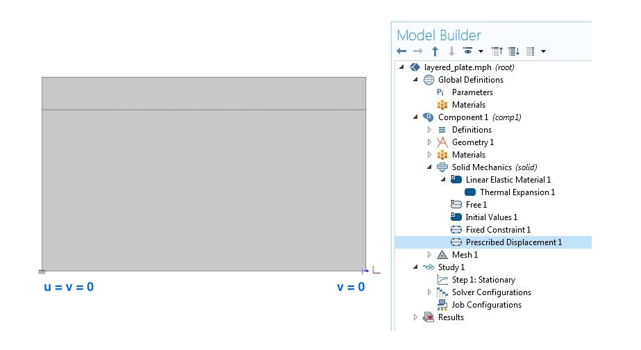
Stabilizing a 2D structure using point constraints.
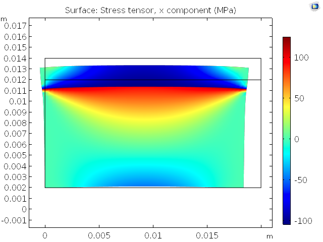
Results after manual prescription of displacement constraints that do not affect the stress state.
While it is possible to follow this approach, it can become tricky in more complicated problems. Consider a structure where the boundaries are not neatly aligned with the coordinate directions, as in the above object. Now, we have to constrain some function of the displacements u and v instead of just v at the second point. This can easily get out of hand in a 3D problem. Also, the degrees of freedom are not always displacements when using other structural mechanics interfaces, such as the Beam interface. Let’s check out a simple and unified solution.
Automatic Rigid Motion Suppression
Irrespective of the spatial dimension or the structural theory (interface), we can use the Rigid Motion Suppression node, which enables the COMSOL® software to take care of the missing displacement constraints. This feature is available as of COMSOL Multiphysics version 5.3. Go to Solid Mechanics > Domain Constraints > Rigid Motion Suppression in the Model Builder to access this node and add domains to it.
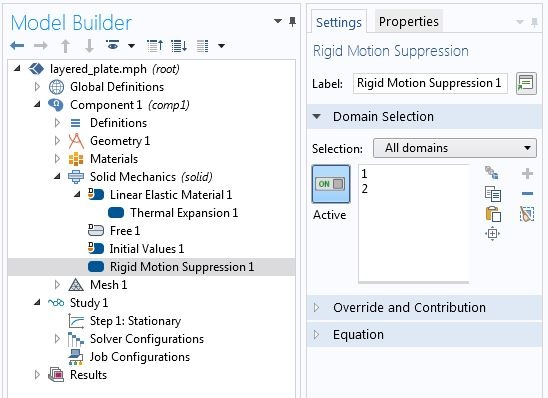
Rigid motion suppression for a 2D problem.
We get the following result with the automatic approach for rigid motion suppression:
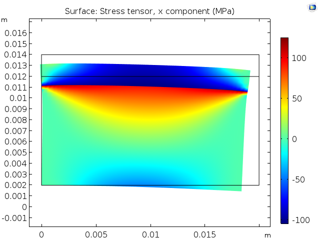
Stress from temperature change and CTE mismatch.
In the solutions above, the stress is the same, but the deformed shapes appear different. In fact, they differ by a rigid body motion. When we provide rigid motion suppression manually, we are picking one out of an infinite number of solutions. The automatic rigid motion suppression can pick another one. As a result, the displacements can differ by a rigid body motion, yet the strains and stresses will be the same.
In the current example, we can add either domain or both to the Rigid Motion Suppression node. Since the two domains are glued, preventing rigid body motion in one domain is enough. In such cases, the choice of domain does not change the obtained stress state. It just changes the points the software decides to constrain.
Let’s now proceed to a 3D problem, where we consider a mix of structural mechanics interfaces and use the Heat Transfer interface to obtain a nonuniform temperature distribution. This example simulates the electrical heat generation, heat transfer, and mechanical stresses and deformations of a heating circuit device.
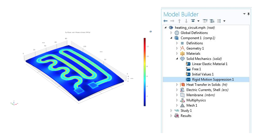
Von Mises stress resulting from the CTE mismatch in a heating circuit.
The algorithm used by the COMSOL Multiphysics software to identify the points and constraints to use with the Rigid Motion Suppression feature is described in the Structural Mechanics Module User’s Guide.
Warning Against Misuse
Often in thermal expansion simulations, temperature change is the only active source of stress. But if there are mechanical forces, these should be self-balancing. The Rigid Motion Suppression feature assumes there is no net applied force. If that is not the case, we need appropriate constraints that provide reactions to balance the applied mechanical forces.
Which Domains Should Be Automatically Constrained?
In an assembly with multiple domains, some domains may not have enough constraints. We do not want to artificially constrain those that are already supported. A convergence error from a stationary analysis does not help us identify which domains are stable and which are hanging free.
In such cases, we can perform an eigenfrequency analysis to find the hanging domains. The modes that correspond to rigid body motion have eigenfrequencies close to zero.
Let’s demonstrate this by using an assembly containing three rectangular domains. The bottom two domains are glued together and the top domain is hanging. We apply a fixed constraint to the bottom-most boundary.
There are three modes with a frequency close to zero, corresponding to the three rigid body modes of the hanging domain. Now we know which domain needs rigid motion suppression.
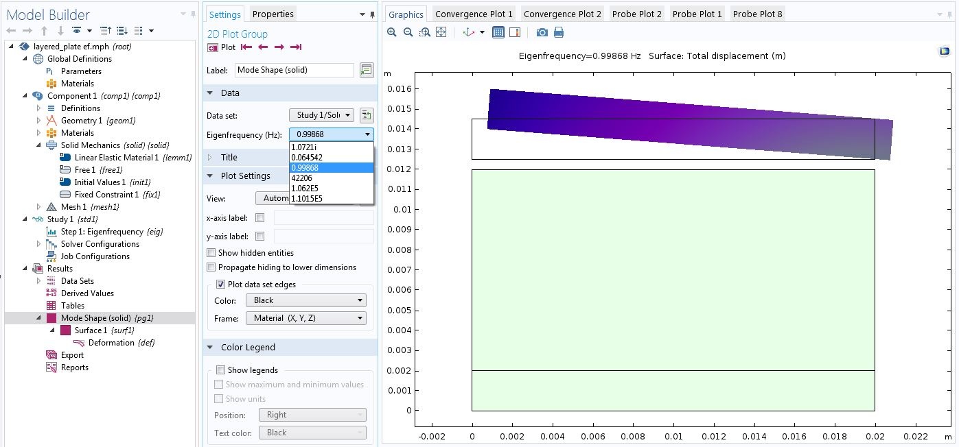
Using an eigenfrequency analysis to identify hanging domains.
Note that a very coarse mesh is enough here. If the motivation for eigenfrequency analysis is identifying hanging domains, only low-frequency modes are sought after. To this end, enough elements that just capture the shape of the object suffice. In subsequent stationary analyses, we want to use a mesh that is fine enough for an accurate solution.
Such hanging domains are often encountered in contact mechanics simulations. Before objects establish enough contact to stabilize each other, some objects can be hanging. In contact simulation, we rarely want these domains to stay in place. In such cases, we use COMSOL Multiphysics features such as the Spring Foundation, which stabilizes the domains without holding them in place. See the “Contact Modeling” section in the Structural Mechanics Module User’s Guide for more information.
Summary
In this blog post, we discussed a frequent source of convergence problems in thermal expansion simulations: lack of displacement constraints. We discussed manual and automatic techniques used to alleviate the issue. The Rigid Motion Suppression condition helps to automate this process and saves time when working with complicated setups. To identify the domains to add to the Rigid Motion Suppression node, we can use an eigenfrequency analysis on a coarse mesh.
Next Steps
- Try out the tutorial models featured in this blog post:
- Read this related blog post:
- Learn more about eigenfrequency analyses




Comments (4)
Ivar KJELBERG
June 29, 2018Hi Kateryna
You have forgotten to mention the very nice “Fixed” boundary condition sub-node : “Thermal Expansion”. It allows to give it a “thermal expansion coefficient” to your “fixed” boundary, that can also help you greatly in many conditions.
This new BC appeared a few versions ago, and I suspect many of the older COMSOL users has overlooked it.
Thanks for nice BLOG 🙂
Sincerely
Ivar
Temesgen Kindo
June 29, 2018Hi Ivar,
Thanks for bringing up the “Fixed Constraint>Thermal Expansion” feature. It is a good feature to know.
By the way our colleague Henrik Sonnerlind discusses that feature in this blog:
https://www.comsol.com/blogs/how-to-analyze-eigenfrequencies-that-change-with-temperature/
Ivar KJELBERG
July 2, 2018Hi Temesgen
Indeed thanks for reminding us about that link, its always interesting to (re)read Henrik’s blogs 🙂
I was one, of the probably many, asking for the implementing of such a feature, as before I programmed it in by hand, BC by BC, via the “Prescribed Displacement” BC, as for the “Spring foundation” ones, by the way.
I will take this opportunity to thank you all at COMSOL, and to incite all end users to send to you their suggestions, documented and justified, so that COMSOL might further add new useful features for us all.
Clearly, we propose, and you implement at your rythm, as it’s essential that COMSOL remains a generic multi-physics program.
It is now more than 45 years since I first learned to program, and to build upon software I (or my university, or company) bought, and so far, COMSOL is clearly the best to listen to your end users and to adapt to our demands, for a common benefit.
So PLS remain like this, on your track for the future, as today you are growing BIG, and that is when its the most difficult to keep the pioneer spirit in a company, to keep the most skillest scientific and programming experts, and not get overwhelmed only by managers and other “bean counters” (some are needed though …) for the next decades.
Bon vent …
Sincerely
Ivar
zoubir bekkari
September 2, 2018Thanks for bringing up the “Fixed Constraint>Thermal Expansion”