
Recently, Tesla Inc., a major electric car and battery manufacturer, announced a new “tabless” design concept for cylindrical lithium-ion batteries. This caused quite a stir among battery pundits. (Ref. 1) Tesla claimed that the innovation brings significant increases in range and power using already existing chemistries. For a battery community used to incremental yearly advances on the single-digit percentage scale, this sounded almost too good to be true. However, digging into the underlying battery physics quickly reveals why this concept could provide extra mileage to our future electric vehicles. In this blog post, we explore this new tabbing design.
Simulating Batteries Using Tabbing
Let’s take it from the beginning: A lithium battery cell is constructed as a sandwich of different layers — current collector metal foils, porous electrodes, and separators — which is placed in an enclosure filled with electrolyte. The configuration of the sandwich depends on the type of enclosure (coin cell, prismatic, pouch, cylinder, etc.). Cylindrical lithium-ion batteries are manufactured by rolling the different battery layers into a cylindrical roll, which is then placed in a metal can. The resulting spiral structure is commonly referred to as a “jelly roll”, due to its resemblance to the pastry from central Europe.
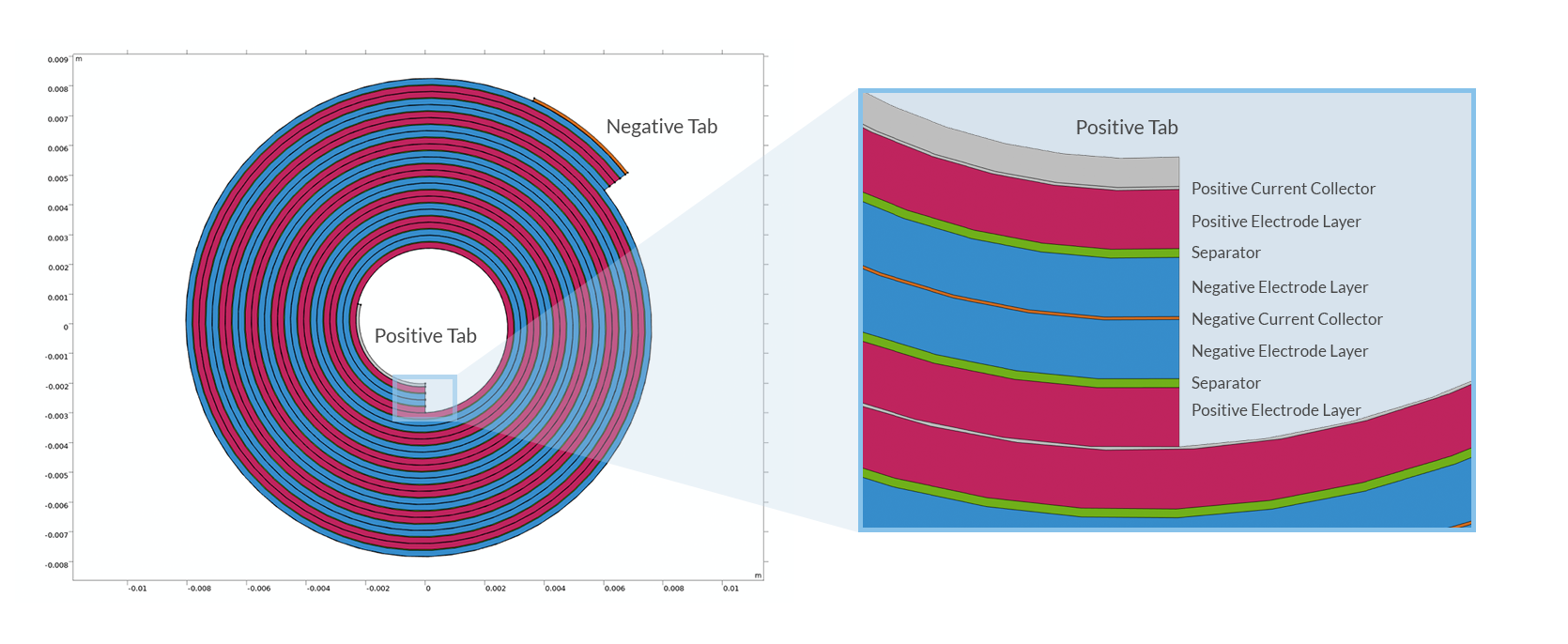
Cross section of a spirally wound jelly roll for a cylindrical battery.
The current collector foils are usually made of copper (negative electrode) and aluminum (positive electrode), both with thicknesses of around tens of micrometers, or less. The reason for the choice of different metals is their electrochemical stability at different potentials. In order to conduct the current to and from the jelly roll to the outside, to the battery can, additional strips of metal, tabs, are welded to the current collectors. The simplest tab design, used in low-power batteries, places one tab on each side of the jelly roll.
As a first approach to investigate the effect of tabbing, we can create a pseudostationary model that accounts for the ohmic voltage losses in the electronic conductors and the electrolyte, as well as the activation overpotentials due to the charge transfer reactions in the electrodes. The resulting internal distribution of the applied battery current under these circumstances is called secondary current distribution by electrochemists. Since the model does not account for accumulation or depletion of lithium atoms in the electrodes or lithium ions in the electrolyte, it can be seen as a snapshot of a battery frozen at a certain state of charge. In reality, local concentration changes over time as the battery is charged or discharged. However, a secondary current distribution model can accurately predict the voltage losses in the jelly roll at a given moment in time at a given state of charge.
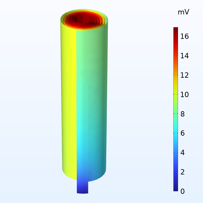
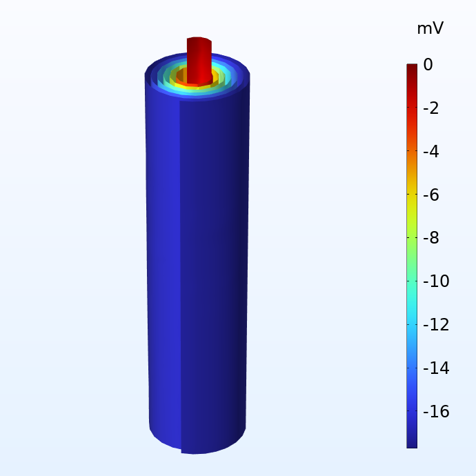
Potential in the negative (left) and positive (right) current collector foils with respect to the corresponding current terminals.
The figures above show the potential distribution in the negative and positive current collectors for a battery jelly roll when subjected to a 1 C discharge. 1 C is the equivalent current required to either charge or discharge the battery in one hour. The size of this jelly roll fits the can of a 18650 battery, which is 65 mm high and 18 mm in diameter. We note that although the potential losses in the current collectors are fairly small, they are not negligible. For a larger cell like the 4680 cell (80 mm high and 46 mm in diameter) which Tesla is planning to manufacture, the potential losses would become substantial with a traditional tab design.
Since our model is physics based, local heat sources can be readily derived based on the ohmic losses (Joule heating) and the activation overpotentials. When plugging our heat source variable into a heat transfer model, we get the results below.
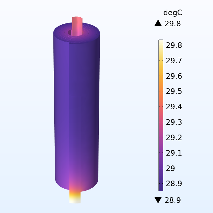
Temperature distribution in the jelly roll.
Here, we apply a convective cooling condition on the outer area of the jelly roll, prescribing a cooling heat flux proportional to the difference in surface temperature and outside temperature (25°C). The heat conducted through the electric terminals at the tab ends is ignored.
If we look at the temperature distribution, we can see a steep increase in temperature in the tabs. This indicates that the Joule heating in the tabs results in significant local heating for this fairly small battery even at moderate currents. The local temperature difference can also propagate into the adjacent electrodes layers, which then results in portions of the battery been aged quicker, then limiting the life of the whole battery.
The true jelly roll geometry is a bit cumbersome to work with when doing modeling and simulations. For example, it is tricky to draw objects in a spiral geometry, such as adding multiple tabs in the interior of the jelly roll. In addition, it is difficult to visualize the results inside the spiral layers, for instance plotting the current density through the separators at different positions in the roll.
Modeling a Flattened Jelly Roll
Alternatively, we can define the same model on a flattened (unrolled) version of the jelly roll geometry. This allows us to easily introduce tabs and to better look at the model and simulation results. Instead, we can virtually roll the battery. Shown in the illustration below is a flattened version of the jelly roll where the different layers and tabs have been drawn as rectangular blocks.
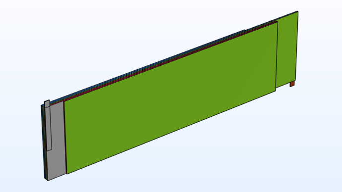
Flattened representation of the spiral jelly roll geometry.
In reality, when creating the jelly roll from the stack of layers, the front (green) boundary ends up in contact with the back side of the stack of the rectangular blocks, see the figure above. Special coupling boundary conditions, so-called nonlocal couplings in the COMSOL Multiphysics® software, are used in the flattened jelly roll model in order to connect these now geometrically detached boundaries together mathematically. This is what we mean above by virtually rolling the battery.
The flattened geometry also has the advantage of requiring fewer mesh elements, since the local curvature of the roll does not need to be resolved. Reassuringly, the temperature profile for the flattened geometry accurately reproduces the results from the jelly roll, see above, indicating that we can perform this flattening transformation with only small effects on the results.
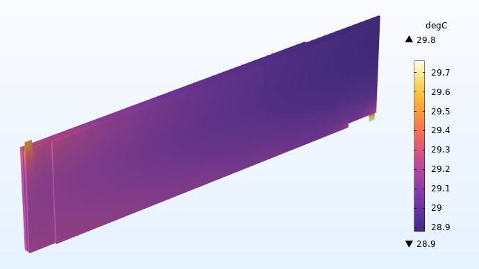
Temperature (°C) in the flattened jelly roll.
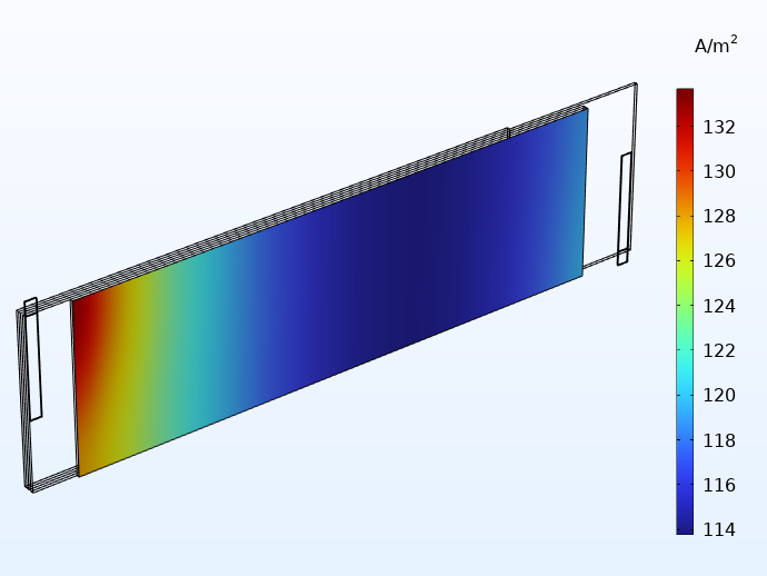
The flattened geometry now allows for easy visualization of the cross-separator current density as shown in the figure below.
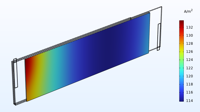
Current distribution (A/m2) in the through-plane direction of one of the separators.
Current distribution plots like this give valuable insights to the battery designer. In this case, the plot shows a significantly higher current density in the area close to the tabs. This implies that the battery is exposed to more electrochemical wear in the areas closer to the tabs, resulting in accelerated aging. If the cell is allowed to run for a longer time, the current distribution plots shown above would eventually even out to a more uniform profile. However, for a battery being cycled for a shorter amount of time around a fixed state of charge (for instance, a load leveling battery system), our assessment of the current distribution above is fairly accurate.
Investigating Integrated Tabbing Designs in COMSOL Multiphysics
Let’s now use the abovementioned modeling approach to investigate the so-called tabless design.
The tabless concept means removing the additional metal strip tabs and instead letting the metal current collector foils conduct the current to the outside. This is achieved by extending the foils to reach outside the electrode areas. Since the foils are very thin, a multitude of these extended foil strips are needed in order to prevent large ohmic resistances. The term “tabless” is actually a bit misleading, since the tabs are integrated into the foils rather than removed entirely. Therefore, we use the terms integrated tabs and integrated tabbing in the remainder of this blog post.
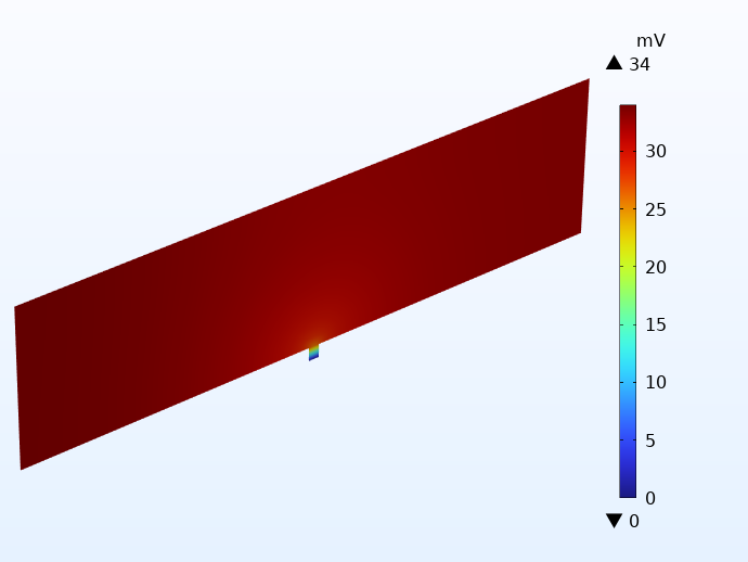
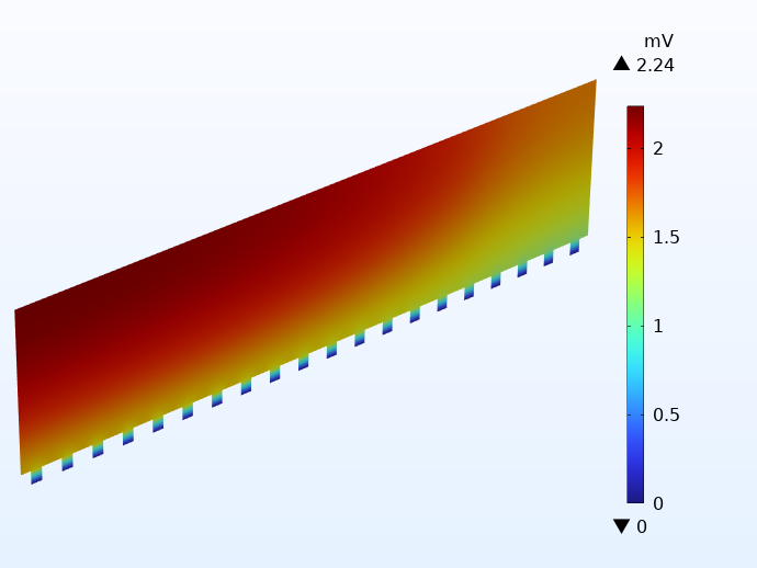
To illustrate how this works in practice, the potential distribution in the negative current collector foil for two cells using integrated tabbing is shown below. Apart from the tabbing configuration, the cells are identical to the examples above. The illustration on the left uses only 1 integrated tab, whereas the example on the right uses 20 tabs on each side. Note the different scales of the potential legends. The difference is more than 30 mV!
A comparison of the electric potential in the negative current collector for two cells using integrated tabbing: 1 tab cell (left) and 20 tabs (right).
Using one integrated tab yields very large potential losses, leading to large local heat sources. As for the cell with many tabs, we get even lower potential losses than for the cell using traditional tabbing.
The example with one integrated tab should be seen as an extreme. On the other hand we want to save metal and battery weight by not using more tabs than required. In order to investigate the impact of the number of tabs, we can perform a parametric sweep study and plot the number of tabs against the total polarization and the maximum temperature of the cell.
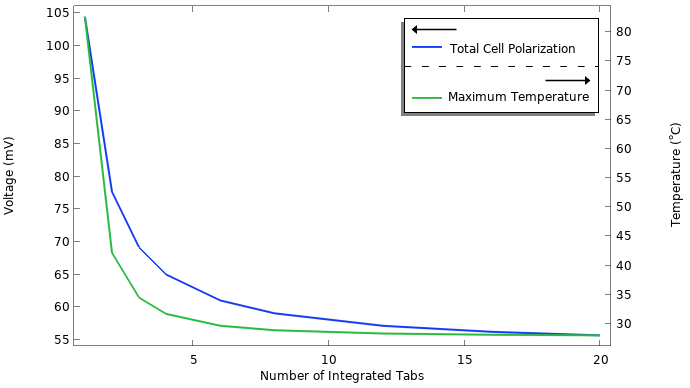
Total cell polarization and maximum temperature versus the number of integrated tabs.
As shown in the graph, we start to approach an asymptote fairly quickly. We can see that adding more than 20 integrated tab strips does not lower the cell polarization below the 55 mV level. This remaining cell polarization stems from other processes that are not affected by the number of tabs, such as the resistance of the electrolyte and the charge transfer reactions. We also see that using only one or two tabs is not an option, since the temperatures reach very high levels. A high temperature accelerates aging and is also a direct safety hazard.
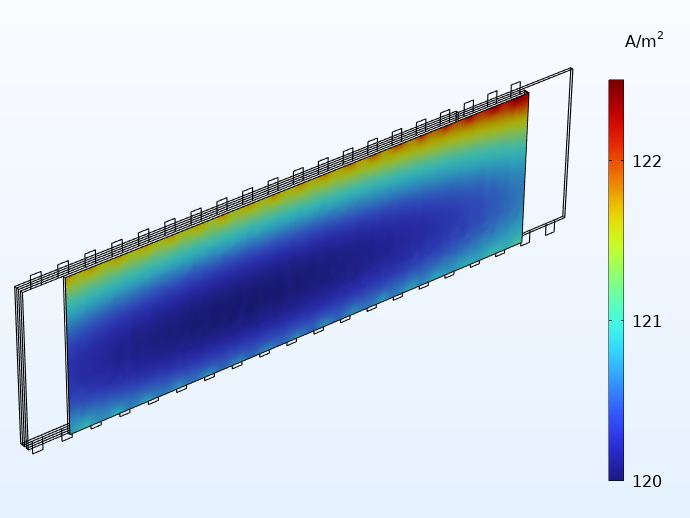
Comparing the current distributions between integrated and traditional tabbing below, we see a more uniform distribution with the integrated tabs. In addition, the small distribution effects that still remain when using integrated tabbing are now mainly seen along the height direction of the jelly roll.
Current distribution in the through-layer direction when using 20 integrated tabs (left) and for traditional tabbing (right).
When it comes to heat transfer, integrated tabbing yields improved interior cooling of the jelly roll. This is because the tabs are in thermal contact with the outside cooling surface through an excellent heat conductor, the metal. Every tab is in thermal and electrical contact with the outside.
The figure below shows a temperature distribution of the jelly roll with integrated tabbing. We can see from this plot that the temperature field is much more uniform here compared to the case with traditional tabbing.
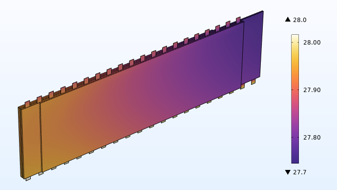
Temperature (°C) distribution when using 20 integrated tabs.
Closing Remarks
In summary, integrated tabbing substantially improves both the conduction of current and the conduction of heat out of the cell. This makes it possible to build cylindrical cells with larger radius, which may also give higher overall energy and power densities of battery packs. A larger battery radius gives a larger ratio between the amount of internal battery material and the external casing (can) of the battery. This also explains Tesla’s intentions and claims.
The “tabless” design proves to be an innovative alternative to traditional tabbing for lithium-ion batteries. However, it also brings new engineering challenges that can be evaluated in the COMSOL Multiphysics software.
Next Steps
- See how the jelly roll method can help your simulations by downloading these tutorial models:
- Check out these related blog posts:
- View Tesla’s presentation on the tabless method
Reference
- A. J. Hawkins, “Tesla announces ‘tabless’ battery cells that will improve range of its electric cars”, The Verge, 22 Sep. 2020; https://www.theverge.com/2020/9/22/21449238/tesla-electric-car-battery-tabless-cells-day-elon-musk




Comments (1)
Dhruva Deole
May 22, 2023Hello Henrik,
Good blog!
Although the dimensions should be corrected, 18650 cells have a ‘diameter’ of 18 mm (here it is mentioned as radius). Same for 21700 or 4680.
Regards,
Dhruva