
If you look up at the night sky, especially somewhere far away from city lights, you will see the stars twinkle. While an inspiration for poets and romantics throughout time, the beauty of the starry night sky has also been a challenge to astronomers studying the night sky and the universe. It has led to the development of adaptive optics, which is used nowadays to improve the power of optical systems beyond the obstacles imposed by the optical medium.
Adaptive Optics: Removing the Unwanted Effects of the Optical Medium
When light from an astronomical object, such as a star, passes through the earth’s atmosphere, the atmospheric turbulence causes the blurring and twinkling (scintillation) of star images. A similar effect happens when you look at an object in a pool or over a fire. It limits the resolution of optical instruments and deteriorates the quality of astronomical images. Astronomers fought the effect of this so-called astronomical seeing for centuries. They tried to escape it by building their observatories on mountaintops and launching telescopes into space.
In an effort to overcome these difficulties, the American astronomer Horace W. Babcock presented the groundbreaking idea of adaptive optics in 1953. This concept was first pursued independently for both astronomical and military applications, but it wasn’t until the advent of modern computer technology that adaptive optics became feasible and accessible for broad science and commercial applications.
Nowadays, adaptive optics is used not only in astronomical telescopes, but also in laser communications; laser material processing; meteorology; military and security applications, such as surveillance; biomedical technology, such as ophthalmology and vision science; in consumer devices to improve the quality of images; and even in robotics vision.
The global adaptive optics market has a turnover of about $40 million and is expected to grow to about $40 billion in 2022, according to this report.
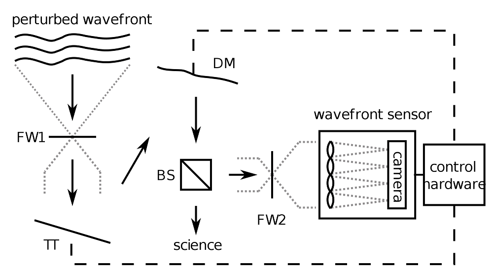
Schematic of an adaptive optics system. The wavefront enters the system at the top. The light first hits a tip-tilt (TT) mirror and is then directed to a deformable mirror (DM). The wavefront is corrected and part of the light is tapped off by a beamsplitter (BS). The wavefront is measured by a wavefront sensor (Shack-Hartmann in this case) and the control hardware then sends updated signals to the DM and TT mirror. The two filterwheels (FW1 and FW2) are used during calibration only. Source: Wikimedia Commons. This file is licensed under the Creative Commons Attribution-Share Alike 3.0 Unported license.
The basic principle is simple but powerful. The adaptive optics system measures the incoming wavefront with a wavefront sensor, calculates the correction, and applies it to the optical component to correct the wavefront in real time. The optical component and a key part of the system is mostly a deformable mirror, which consists of an array of actuators connected to an optical surface that deforms according to the movement of the actuators.
Deformable mirrors can be based on different actuation methods, such as magnetic, electrostatic, or piezoelectric methods. Today, micro-electro-mechanical systems (MEMS) deformable mirrors are the most commonly used technology. Recently, some new concepts are being explored, such as micro-optical-electro-mechanical systems (MOEMS) and ferrofluid mirrors.
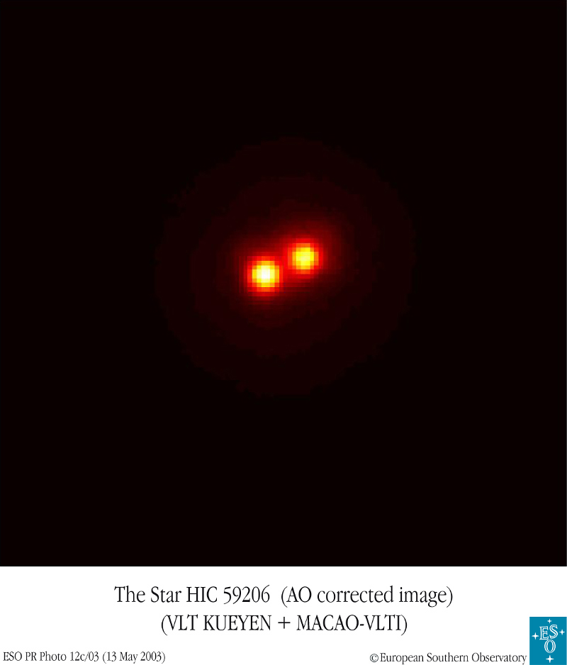
The image of the star HIC59206 made with the Very Large Telescope as corrected with an adaptive optics system. Source: Wikimedia Commons. This file is licensed under the Creative Commons Attribution-Share Alike 3.0 Unported license.
Modeling Adaptive Optics Systems with COMSOL Multiphysics Simulation Software
The design of adaptive optics systems, especially deformable mirrors with different MEMS actuators, can benefit from the power of multiphysics modeling. The COMSOL Multiphysics simulation software platform is the ideal tool for modeling the key components in such adaptive optics systems.
Not surprisingly, adaptive optics, in particular its application in astronomical systems, has already been a highlighted topic at several of our user conferences. Modern astrophysics is a high-tech science that profits from a strong connection between industry and research to solve various engineering challenges in ambitious scientific projects.
One such scientific and engineering challenge is the development of large advanced telescopes with the mirror diameters ranging from a few meters to as much as 40 meters. For example, the Thirty Meter Telescope, currently under construction at the Mauna Kea observatory in Hawaii, will have an optical performance nearly ten times better than the Hubble Space Telescope, thanks to its innovative adaptive optics system. Another giant telescope, which is being built in Chile, is the 39-meter-long European Extremely Large Telescope — one of the mirrors will involve over 6,000 actuators deforming its shape a thousand times a second!
Users Shared Their Research at the COMSOL Conference
At the COMSOL Conference 2012 in Milan, a team of scientists from the Arcetri Astrophysical Observatory and the University of Cassino and Southern Latium in Italy presented a paper on using COMSOL Multiphysics to design an adaptive optics actuator called the Variable Reluctance Adaptive mirror Linear Actuator (VRALA), which is based on a magnetic circuit.
Operating an adaptive mirror for a ten-meter-class telescope on visible wavelengths requires the mirror to be more slender and faster than on other wavelengths. VRALA is the ideal candidate for the actuators at those wavelengths. The team used COMSOL simulation software in the design process for electromagnetic, mechanical, and thermal studies.
At the COMSOL Conference 2013 in Rotterdam, a team from the Arcetri Astrophysical Observatory and two Italian companies, ADS International and Microgate, presented their studies on deformable mirrors from the Large Binocular Telescope located in Arizona and the Very Large Telescope in Chile.
The actuator geometries found in their adaptive optics systems are complex. The deformable mirror of the VLT has, for example, 1,170 actuators. The team used COMSOL Multiphysics and LiveLink™ for MATLAB® to calculate the so-called influence functions showing the deformation that any combination of actuators would produce.
At the more recent COMSOL Conference 2014 in Cambridge, a team from the Arcetri Astrophysical observatory presented once again. This time, they showed how they used COMSOL Multiphysics and LiveLink™ for MATLAB® to match simulated influence functions with the measurements, thus validating the simulations. You can find these papers here and here.
At the COMSOL Conference 2014 in Boston, a team of scientists from the NASA Goddard Space Flight Center and two U.S. companies, the Newton Corporation and Iris AO, Inc., showed how they used a finite element model developed with COMSOL software to perform structural mechanics simulations of a MEMS mirror segment. This mirror segment, called the Multiple Mirror Array, will be used as a key component in the instrument called the Visible Nulling Coronagraph, which is intended for the detection of Earth-size exoplanets. The team also used the COMSOL Multiphysics model to predict the dynamic behavior and stresses of the segment when undergoing mechanical shock during a spaceflight.
Modeling Examples of MEMS Components and Devices
The MEMS Module provides modeling tools to efficiently simulate different types of MEMS components and devices, including MEMS actuators.
In such devices and at small scales, it is necessary to consider couplings of different physical phenomena, such as electromagnetic-structure, thermal-structure, or fluid-structure interactions. Thus, MEMS devices represent truly multiphysics applications.
Electrostatically Actuated Cantilever
In the Model Library and our online Model Gallery, you can find several COMSOL Multiphysics example models relevant to adaptive optics systems.
For instance, the model of the electrostatically actuated cantilever shows the bending of an elastic cantilever beam due to electrostatic forces. The Electromechanics interface found in the MEMS Module allows the calculation of the elastic deformation of a cantilever beam in response to electrostatic forces, which are induced by an applied potential between the cantilever and the substrate beneath it.
As the cantilever bends, the forces are modified, since the shape of the gap between the two surfaces changes. The deformation of the gap region is tracked by the built-in moving mesh functionality (such functionality can also be referred to as ALE or Arbitrary Lagrangian Eulerian) in COMSOL Multiphysics. The COMSOL simulation software computes the electrostatic forces in a self-consistent manner throughout the process.
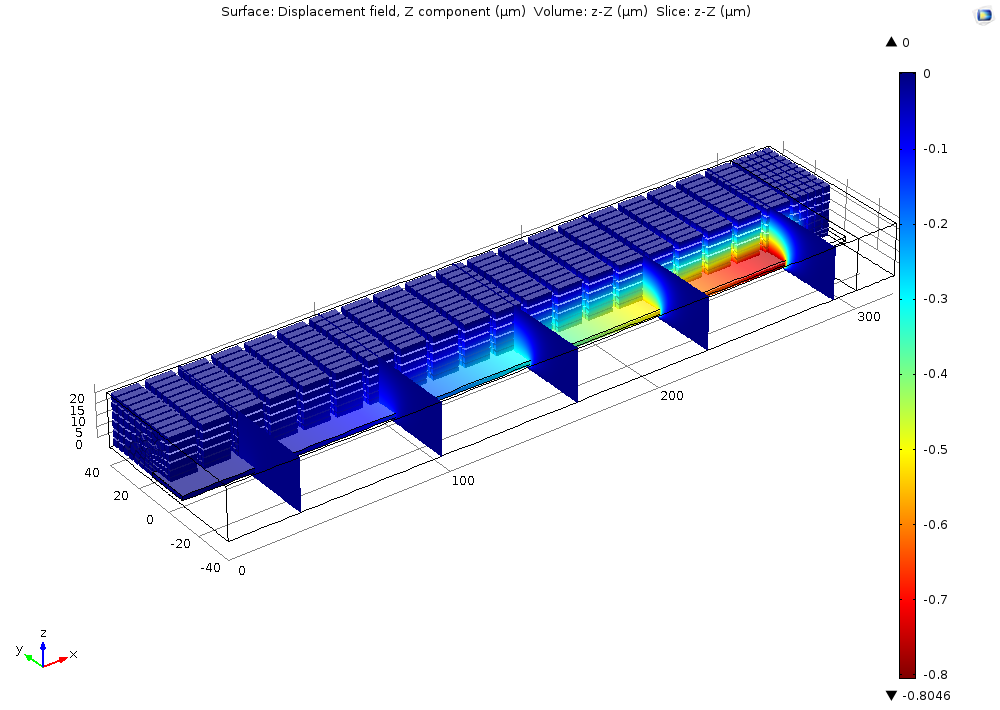
Displacement in an electrostatically actuated cantilever.
Electrostatically Actuated MEMS Resonator
Using the same Electromechanics interface, you can also perform a modal, frequency, and transient analysis of a MEMS cantilever. You can also estimate the critical voltage, or the pull-in voltage, when the system becomes unstable. The sequence of models of the electrostatically actuated MEMS resonator shows how to characterize such microelectromechanical resonators, for example by calculating normal modes and a frequency-dependent response of the system. For tutorial purposes, these models are also available in 2D.
Residual Stress in a Thin-Film Resonator
You can also model thermal residual stress in thin-film resonators, which are often a result of the fabrication process. Using the Solid Mechanics interface, the Thermal Expansion feature, and the Eigenfrequency study feature, you can calculate how the thermal stress changes the resonant frequency of the thin-film resonator.
Prestressed Micromirror
Another example is the model of a prestressed micromirror. Such a mirror could be used as an optical reflection device. To create curved surfaces or a spring-like structure, MEMS device manufacturers sometimes use the plating process to introduce a residual stress in the micromirror. The example demonstrates how to set up such model and include initial stress and strain in the model. You can also see how the deformed structure differs for different materials, such as aluminum and steel.
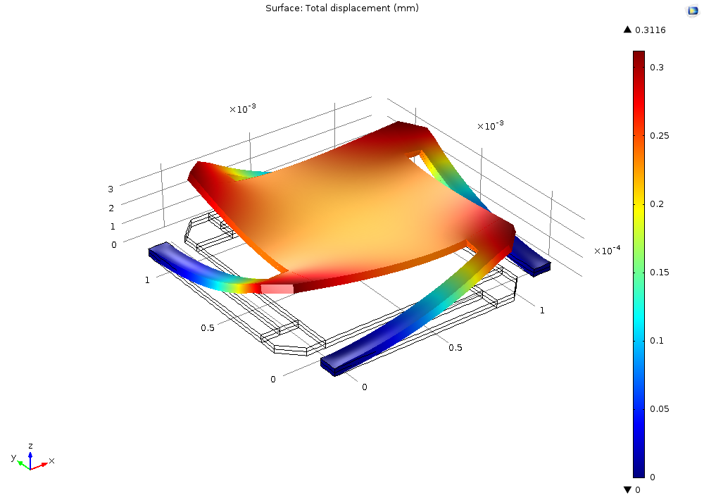
Micromirror deformation and lift-off for aluminum.
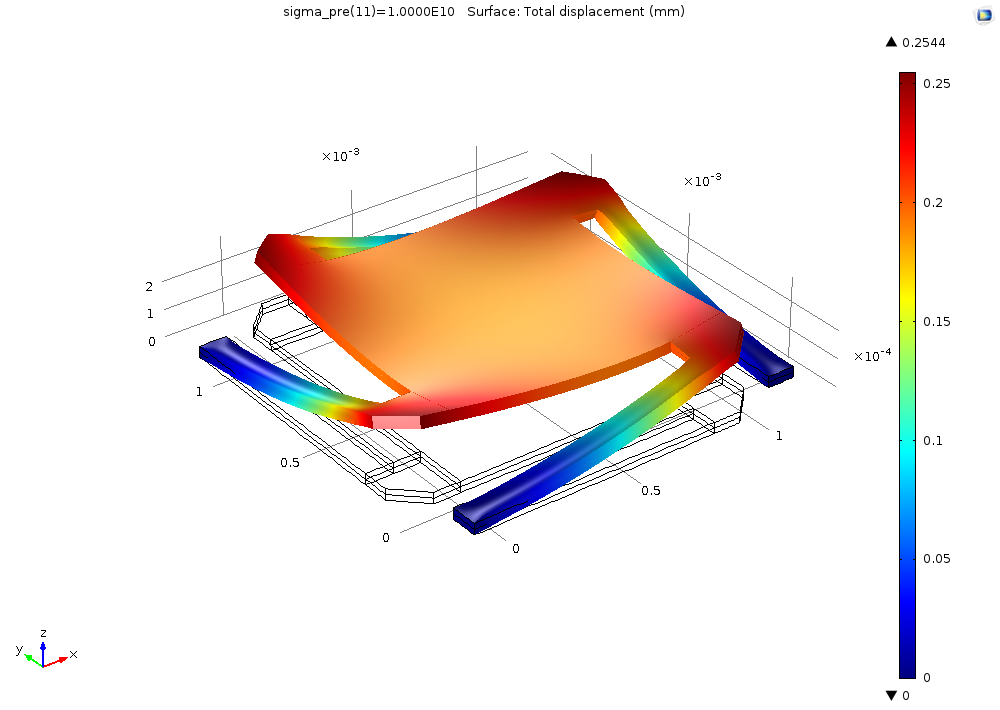
Micromirror deformation and lift-off for steel.
Including Optics in Your Models
COMSOL Multiphysics also offers a number of other capabilities to perform optical simulations and couple them with mechanical, thermal, or other simulations of MEMS components.
The Wave Optics Module provides dedicated tools for high-frequency electromagnetic wave simulations in optical media by way of the innovative beam envelopes method. You may also couple structural mechanics with wave optics simulations, like in this cavity model or in this waveguide simulation.
The new Ray Optics Module can be used to model light propagation in optical media and devices, treating electromagnetic waves as rays. You have a number of ray optics examples at your disposal, including the model of a corner cube retroreflector or light propagation in a Newtonian telescope.
MATLAB is a registered trademark of The MathWorks, Inc.


Comments (0)