Wireless power transfer involves the transfer of power between a transmitting and a receiving unit and is used to wirelessly charge electronics like mobile phones and electric cars. While wireless power transfer offers many benefits, there are some challenges that this technology encounters. This is where simulation comes in handy. For instance, some WPT technologies must be oriented in a certain way to ensure proper performance. Today, we’ll analyze the impact of orientation on the functionality of two WPT antennas.
An Introduction to Wireless Power Transfer Technology
Electronic devices are a key component in our day-to-day lives. Imagine if it were possible to charge these devices without the need for wires or cords. The development of wireless power transfer (WPT) technology is making this possible, offering a simplified approach to charging electronics, including the ability to charge multiple devices at once. As the technology continues to grow, charging electronic devices wirelessly is becoming a reality in more and more applications, from phones to electric cars.

Wireless charging spots at a coffee shop. Image by Veredai from Powermat Technologies — Own work, via Wikimedia Commons.
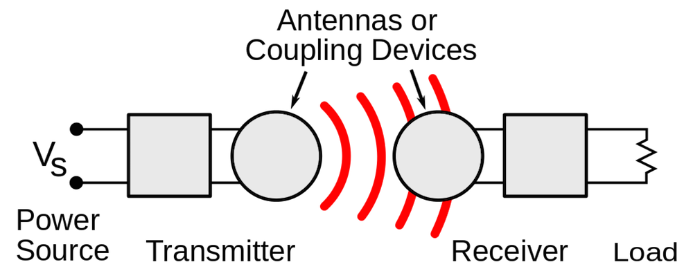
As previously noted, WPT offers ubiquitous power by transmitting electrical power without the use of solid wires or conductors. Generally, this is achieved by using an electromagnetic field to transfer energy between two separate objects. Here, a power transmitting unit (PTU), which is connected to a power source, generates a magnetic field and a power receiving unit (PRU) captures this energy and converts it into usable power.

A simple illustration of wireless power transfer. The PTU is shown on the left and the PRU is shown on the right.
For some WPT systems, an important concern is that the orientation between the PTU and PRU can greatly affect the energy coupling. As such, a device may have to be carefully aligned on a PTU in order for it to charge. But at what point does a lack of alignment between a PTU and a PRU impede the energy coupling?
Here, we’ll use simulation to investigate how a change in orientation affects wireless power transfer antennas.
Analyzing Wireless Power Transfer Antennas
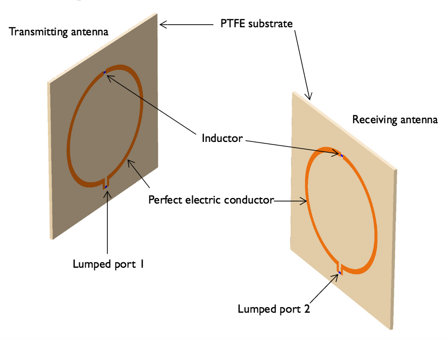
The wireless power transfer tutorial presented today analyzes the energy coupling between two circular loop antennas. In this example, the antennas are made of a polytetrafluoroethylene (PTFE) board and have a thin copper layer on top, which is modeled as a perfect electric conductor (PEC). Each of the devices feature a lumped inductor and a lumped port that can excite or terminate the antenna.
The antennas have a UHF RFID operating frequency of 915 MHz and a shape that inherently provides the ability to perform inductive coupling.

The model geometry. Note that the air domain and perfectly matched layers (PMLs) are not included here.
In our simulation, the receiving antenna is rotating and the transmitting antenna maintains a fixed location. This set up is similar to having a fixed position for a charger, but placing a mobile phone on it at different angles.
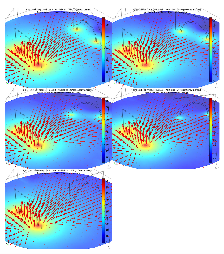
The changing orientation allows us to identify the impact a change in position has on the energy coupling. To visualize this effect, we model the E-field norm distribution and the power flow from the transmitting antenna at different rotation angles of the receiving antenna.

The E-Field norm and power flow (arrow plot) of our wireless power transfer antennas.
The results show that when the antennas are facing each other, which occurs when the receiving antenna’s angle of rotation is 0 degrees, the fields are strongly coupled — an indication of successful wireless power transfer. However, by the time the receiving antenna reaches 90 degrees of rotation, we don’t observe any distortion when the power flow penetrates the receiving antenna. At this rotation, there is almost no coupling or hot coupling area. As such, we can conclude that the power transfer between these two antennas is greatly reduced at this angle.
In the future, we can increase the functionality of WPT antennas by creating systems that function at a wide rage of orientations, enabling the charging of electronics without concern for their particular placement.
Next Steps
- Download the tutorial model: Simulating Wireless Power Transfer in Circular Loop Antennas
- Read a user story about wireless power transfer on page 8 of the 2015 Multiphysics Simulation IEEE insert


Comments (1)
BDavis
April 1, 2018Is it possible to post the tutorial model files for this simulation in an earlier version of Comsol – specifically, Comsol 5.0?