
One of my colleagues raised an interesting question about the losses in three-phase power transmission. It turns out that certain geometric arrangements of the conductors in a transmission line will lead to an imbalance of losses between the wires, even though the structure appears to be symmetric. We built a simple model to demonstrate this, and today we’ll go through how to verify this counterintuitive result.
An Imbalance of Losses, but Why?
Let’s suppose that we have three identical copper wires that are equally spaced in a horizontal line, carrying three-phase power. What will the losses be in each wire? This situation is shown in the schematic below at left. We assumed that the wires are very long and of constant cross section, so we reduced the model to a 2D cross-sectional model, solved in the frequency domain. We modeled each wire in the COMSOL Multiphysics® software using the Coil domain condition as well as complex numbers for defining applied currents that are 120° out-of-phase with each other. For an in-depth tutorial on the modeling of three-phase transmission lines, see our Cable Tutorial Series. It’s worth remarking that the currents going through all three wires sums to zero, so we don’t need to concern ourselves with any current return path along a boundary. The loss distribution within each wire is shown in the figure below at right.
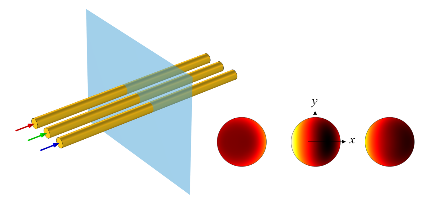
A schematic of three parallel wires carrying three-phase current, along with a plot of the losses in cross section.
In this plot, we can see that the loss distribution is symmetric about the x-axis, but not the y-axis. This might seem unusual since the geometry is clearly symmetric about both axes. So, how can we explain this result?
Starting with a Different Case that is Balanced
There are many different ways of puzzling through this behavior. Here, we’ll start by applying a geometric change that will make things simpler to understand, and then we’ll see where that understanding leads us. Let’s rearrange the conductors into an equilateral triangular arrangement, as pictured below at left. Solving this case shows that all conductors have the same total loss and the same distribution of losses. It’s also worth noting that the loss distribution is rotationally symmetric. That is, rotating the fields 120° around the centroid gives the same distribution. Now let’s work on understanding why the fields are symmetric and see how that helps us understand the original case.
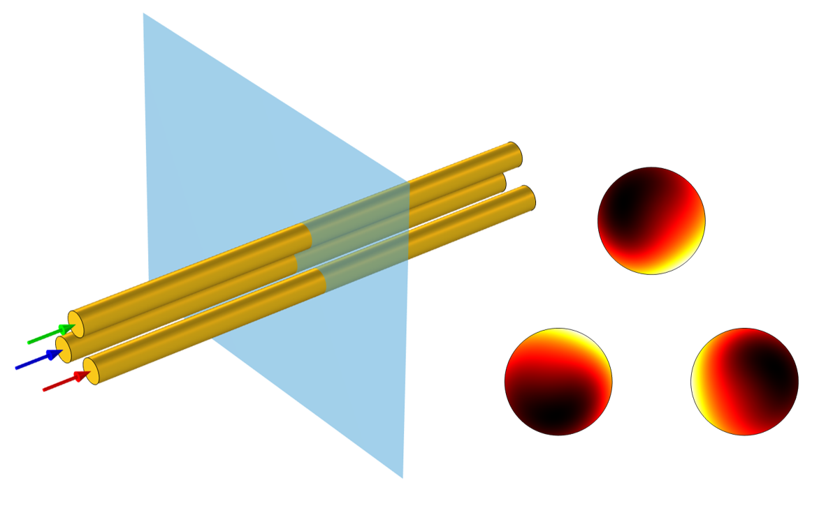
Three wires arranged in an equilateral triangle exhibit balanced losses.
When AC current is driven through a single wire, the resultant time-varying magnetic field induces currents within the wire itself. These back-induced currents tend to oppose the driving current, especially within the center of the wire, which leads to the so-called skin effect. In addition to the back-induced current on the wire itself, the proximity effect leads to the driving current inducing currents in the two neighboring conductors. We’ll state, albeit without a formal proof, that these induced currents in the neighboring wires are:
- Identical in magnitude, since the neighboring two conductors are equally sized and spaced
- 120° out-of-phase with each other
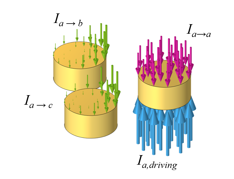
Looking at just the driving current in one of the wires, it induces a current back into the wire itself, as well as the two adjacent wires.
When three-phase current is being driven through all three wires, the total current through one of these three wires is the sum of the driving current in that wire; the back-induced current; and the induced currents from the neighboring wires, e.g., I_{a,tot}=I_{a,driving}+I_{a \rightarrow a }+I_{b \rightarrow a}+I_{c\rightarrow a }. The applied voltage needed to drive the three-phase current is proportional to the driving current and is given by: V_{a}=I_{a,driving} R, where R is the DC wire resistance. When using the Coil feature to drive these wires, an additional Global Equation is added to the system of equations. This will solve for the voltage that will induce the desired total current. The total losses in each wire are given by: Q_a = \frac{1}{2} \Re \left( I_{a,tot} V_a \right), where the currents and voltages are complex-valued and 120° out-of-phase with each other.
Let’s now plot these currents in the complex plane, which helps us visualize how these three back-induced currents sum up to the total current. We don’t actually know the true magnitude or phase of any of these terms, but we know that the phase of the induced currents from the two neighboring wires are 120° out-of-phase with each other. We can also reasonably assume that the relative magnitudes of the currents are: |I_{a,driving}| > | I_{a \rightarrow a } | > | I_{a \rightarrow b}| = |I_{a\rightarrow c } |. This information and assumption allowed us to make the sketch below.
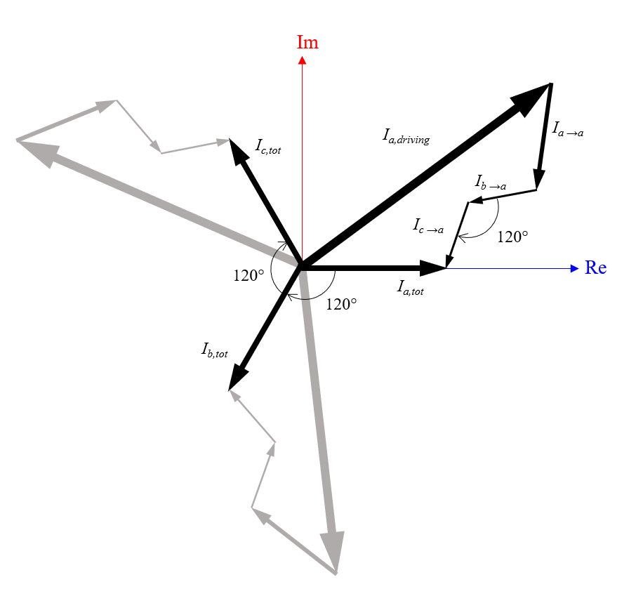
The sum of the driving current, back-induced current, and current induced from other wires will give the total current. For identical wires arranged in an equilateral triangle, these three currents are equal in magnitude and 120° out-of-phase with each other.
Let’s consider the complex-valued driving voltages fixed on all wires and think about what happens when we move the wires from their equilateral arrangement to a linear arrangement. We’ll label the center wire as a. The back-induced currents, e.g., I_{a \rightarrow a }, will not change, and the induced currents from the central wire to the side wires will still be equal in magnitude: | I_{a \rightarrow b}| = |I_{a\rightarrow c } |. The induced currents from the wire on one side to the central wire and the other outer wire will be different: | I_{b \rightarrow a}| \ne |I_{b\rightarrow c } | and | I_{c \rightarrow a}| \ne |I_{c\rightarrow b } |. The magnitude of the induced currents between the outer two wires, though, will be the same — | I_{b \rightarrow c}| = |I_{c\rightarrow b} | — and the relative phases stay constant. We can now plot out the sum and compare the triangular and linear arrangements.
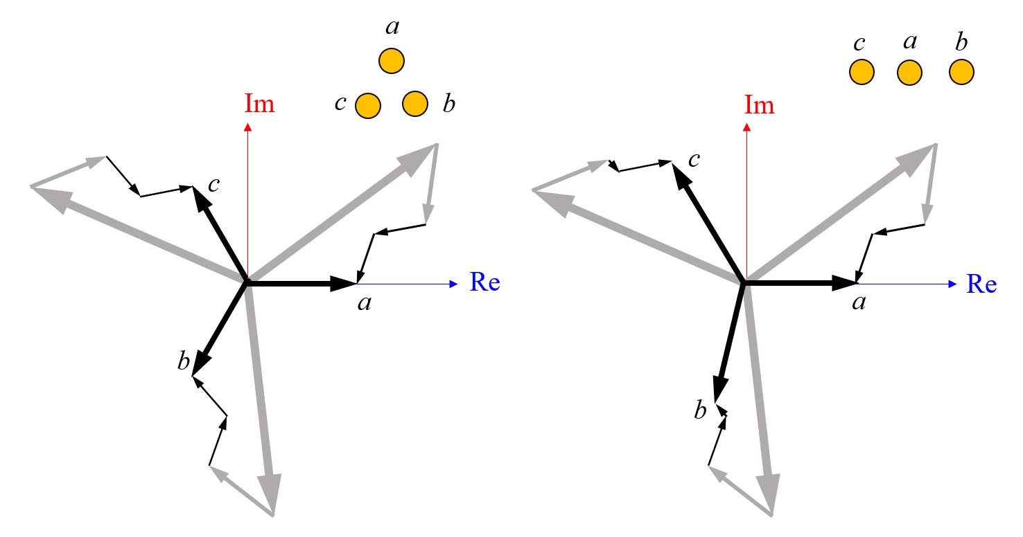
On the left, the sum of the currents for the triangular configuration is symmetric. On the right, the driving voltages are held constant but the wires are moved into a linear configuration, so the induced currents become different in magnitude and the symmetry is broken.
We see that balanced three-phase applied voltages must lead to unbalanced currents. Or, if we turn back to our original case and want to obtain balanced currents, the applied potentials must all be different. Hence, the losses cannot be the same.
Closing Remarks
If one were to physically verify this system, the easiest thing to measure would be the total losses in each wire. The experimentally measured total losses on the outer two wires will be nearly the same, and it would be easy to ascribe this small difference to experimental error. It’s only when you look at the numerically computed distribution of losses, as in the image we started with, that the differences becomes more apparent. However, receiving experimental verification of the loss distribution within the interior of a solid wire is going to be quite challenging, and it might be that no such experiment has ever been done.
It’s also worth remarking that this is one of many different ways of thinking about the problem. You could also make the argument that despite the fact that there is geometric symmetry about the x– and y-axes in the original case, but that the symmetry condition admits only fields that are 180° out-of-phase, a two-fold symmetry. A solution with wires 120° out-of-phase requires a three-fold symmetry, such as the equilateral arrangement. It’s also important to concede that what we have shown here are not formal proofs and that one should question even the most elementary results, no matter how visually attractive they are. So, although we have presented a couple of informal proofs, is that enough?
Another proof is in the model itself. The original model we started with is simple: three wires in a line, carrying three-phase current, solved via the finite element method on a domain that is free of singularities. Sometimes, the results of even a simple model will disagree with our intuition. That will often lead people to suspect an error in the model, which is certainly reasonable since every model should be approached with a modicum of skepticism and a rigorous verification and validation process. We might even be tempted to doubt the finite element method itself, despite it being one of the most used and verified methods in mathematical physics.
In closing, we must not fall into the trap of trusting our intuition too much. Some of the most remarkable discoveries in science start with an unexpected observation, so always keep an open mind!


Comments (7)
Luiz Fernando de Oliveira
July 27, 2022What a fascinating post.
I’ve even created a name for this effect: “three-phase in-line anomaly”. In the last 10 years, I’ve seen it happen a few times in simulations, for different physics:
– losses in transmission line conductors (as in your example);
– magnetic field above sidewalks due to underground distribution lines (with three-phase in-line arrangement);
– losses in steel walls due to three-phase conductors, also in line (parallel to the steel walls).
I had some suspicions that coincide with what was presented in this post, so it was easy for me to accept them. Although, as you comment, I should doubt both, until I find a rigorous proof.
Walter Frei
July 27, 2022 COMSOL EmployeeThank you for sharing Luiz, that is interesting to hear.
Blackcat Blackcat
August 2, 2022There are mainly two types of losses in transmission lines: technical losses and non-technical losses. In technical loss we have radiation loss, conductor loss, dielectric heating loss, coupling loss and corona loss.
John Doe
September 3, 2022I was looking through the cable tutorials and videos and noticed that COMSOL may not be accounting for the circuit configuration. The circuit connections of the phase and neutral wires would have a role in the final solution for current density. Is the circuitry accounted for in these simulations?
Walter Frei
September 6, 2022 COMSOL EmployeeThis is a bit of an open question to address without more context, and can be addressed via the COMSOL Support Team (https://www.comsol.com/support )
Sven Friedel
November 2, 2022 COMSOL EmployeeThanks for the blog, Walter. As a side note: the counter-intuitive asymmetry in does not only apply to losses but also to EM forces, for instance 3- or more phased linear motors and transformers with coils with linear arrangements.
Kevin Goddard
March 22, 2024We can confirm that the asymmetry is not caused by modelling errors by solving for the real and imaginary parts of the driving currents separately. This allows separate calculation of the symmetric and anti-symmetric loss components.
When I do this, the unexpected symmetric components of the anti-symmetric calculation and anti-symmetric components of the symmetric calculation are of the order of 0.05 W/m (in my model). For comparison the expected anti-symmetric components of the anti-symmetric calculation are around 0.7625 W/m in the outer conductors.
The symmetric loss density is given by,
real(mf.Jz)*real(mf.Ez)+imag(mf.Jz)*imag(mf.Ez)+real(mf2.Jz)*real(mf2.Ez)+imag(mf2.Jz)*imag(mf2.Ez),
while the anti-symmetric loss component is given by,
real(mf.Jz)*real(mf2.Ez)+imag(mf.Jz)*imag(mf2.Ez)+real(mf2.Jz)*real(mf.Ez)+imag(mf2.Jz)*imag(mf.Ez).