What happens when you place a vibrating conductive object in a static magnetic field? The magnetic field will induce a current in the moving solid and the charges moving through a magnetic field will experience a force. The resultant force acts to oppose the motion of the structure, which will lead to damping.
Modeling Example: Damping a Vibrating Cantilever Beam
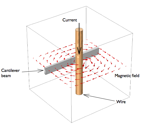
Let’s consider a cantilever beam in a magnetic field, as shown below. It is assumed that there is some structural excitation at the free end of the beam that vibrates the beam at a constant frequency. The magnitude of this excitation is quite low and, as a consequence, the displacements will be small. We will also assume linear elastic material behavior and thus model the structural problem in the frequency domain. However, even though the displacements are small, the velocity (which is the time-derivative of displacement) can be quite large.
From the point of view of the electromagnetic problem, we also assume that the displacements of the beam are small — that is, the magnetic field lines will not change as the beam vibrates. As a consequence, we can compute the magnetic fields with the beam in its unperturbed position. We consider a modeling domain consisting of the beam and a current-carrying wire. An air box around the two encloses the modeling space, and the air box is assumed to be truncated by a good electric conductor — that is, the system sits inside a metallic box.
Now, although the beam itself is assumed to have infinitesimal displacements, its velocity is of importance, especially at high vibrational frequency. A good conductor moving through a static magnetic field, \mathbf{B}, will experience induced currents, \mathbf{J}_i, given by:
where \sigma is the material conductivity and \mathbf{v} is the velocity of the conductor. Due to the effects of magnetic induction, there will be an additional current density contribution stemming from induced fields
Thus, the total current affecting the conductor is
It is assumed that the induced fields are relatively small compared to the static magnetic field and second-order effects are neglected. The currents in the beam will interact with the static magnetic field due to the current-carrying wire and exert a local force on the conductive beam (a Lorentz force):
This force acts to oppose the velocity of the material, leading to a damping of the vibrations. The lost vibrational energy is dissipated as an ohmic heat loss:

The system under consideration: A vibrating conductive beam next to a wire carrying a large DC current.
Coupling the Magnetic and Electric Fields and Solid Mechanics Interfaces
So, does the magnetic field provide significant damping of the beam? Let’s turn to COMSOL Multiphysics, the AC/DC Module, and the Structural Mechanics Module to find out. (Note that we could use the Acoustics Module or MEMS Module instead of the Structural Mechanics Module.)
In our modeling example, we will assume the following to be true:
- The driving current in the wire and the resultant background magnetic field remain constant over time
- The relative magnitude of the structural displacements of the beam is small
- The magnetic fields arising from the induced currents are small relative to the background field
- The material has isotropic and linear properties
Under these assumptions, we can pose the following question: How much damping will the vibrating metallic beam experience due to different background magnetic field intensities?
In order to answer this question, we will need to couple two Magnetic Fields interfaces and one Solid Mechanics interface.
The model is set up in two steps. First, we compute the static magnetic field due to the current-carrying wire next to the cantilever beam using a Stationary study. In the second step, the current induced by the combination of structural vibrations and the static magnetic field is entered as an external current density in a second time-harmonic magnetic field analysis. Here, we solve for the harmonically generated currents coupled to the (small) displacements of the cantilever beam for a range of harmonically excited loads using the Solid Mechanics interface and a Frequency Domain study. We can set up additional variables with the graphical user interface to define the induced currents and the Lorentz force. This force vector can be applied as a body load for the structural problem. In addition, the strength of the magnetic fields is varied using the Parametric Sweep study. This lets us observe the effect of magnetic damping on the oscillating beam for different magnetic field strengths.
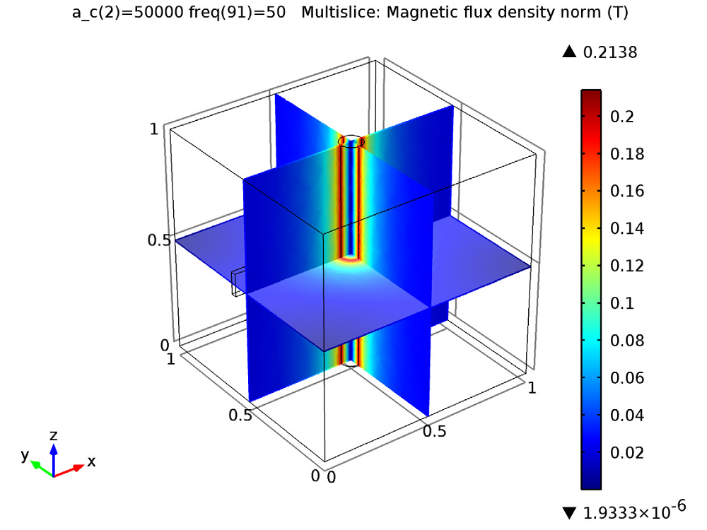
First, we can simulate the magnetic flux due to the current flowing through the wire. As the current through the wire increases, the magnitude of the magnetic flux increases.

The magnetic field due to a constant current flowing through the wire.
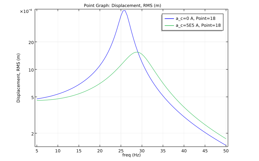
Next, we plot the cantilever beam’s tip displacement versus structural excitation frequency for different magnetic field intensities. As shown in the graph, the beam is significantly damped by the stronger magnetic field.

Tip displacement versus excitation frequency for different magnetic field strengths.
Model Download
- Learn how to build this model by downloading it from our Model Gallery: Magnetic Damping of Vibrating Conducting Solids


Comments (0)