
Today, we will introduce the concept of residual stresses in structural mechanics and find out how to compute them by taking the example of a deep metal drawing process. First, we will explain how they can be computed and interpreted in a bending beam example with or without work hardening. Then, we will introduce a sheet metal forming model.
What Are Residual Stresses?
Residual stresses are self-equilibrating stresses that remain after performing the unloading of an elastic-plastic structure. During the manufacturing process of a mechanical part, residual stresses will be introduced. These will influence the part’s fatigue, failure, and even corrosion behaviors.
Indeed, uncontrolled residual stresses may cause a structure to fail prematurely. Although residual stresses may alter the performance, or even lead to the failure of manufactured products, some applications actually rely on them. For instance, brittle materials, such as glass in smartphone screens, are often manufactured so that compressive residual stresses are induced on the surface to avoid crack-tip propagation.
For these reasons, residual stresses play an important role in mechanical projects as a whole. Only through qualitative and quantitative analysis of these stresses is it possible to determine the most suitable machining processes for a given application. These types of analyses also help you discover the optimal amount of material to be used for their reliability or the most suitable shape that needs to be designed, in order to avoid malfunctions and failures.
Beam Under Pure Bending
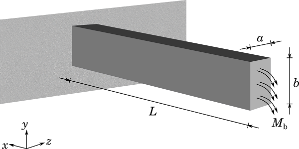
Let’s consider the following slender beam with a rectangular cross section, depth a, and width b. The beam is fixed at the left-hand side and a bending moment is applied on the free end.
Computing Residual Stresses
Based on the beam theory, it turns out that the bending moment is constant in this case and the stress can be written as:
(1)
where I_z is the moment of inertia about the z-axis.
As M_\mathrm{b} increases, the beam first behaves in an elastic manner, but after reaching its yield moment, M_y, it begins to take on plastic behavior. This leads to an elastic-plastic cross section. Once the plastic zone has propagated through the entire cross section, the ultimate bending moment, M_\mathrm{ult}, that the beam can carry is determined. Here, it is assumed that the beam will collapse at such a moment and that it has a perfectly plastic behavior.
The outer fibers of the beam will reach the yield point first, while the core fibers remain elastic. Thus, the previous equation applied to the outer fibers of the beam provides the first yielding moment:
(2)
where \sigma_\mathrm{yield} is the yield stress.
Under an elastic-plastic moment, M_\mathrm{ep} < M_\mathrm{ult}, the plastic zone propagates through the thickness by a distance of h_\mathrm{p} at each side of the beam, as shown below.
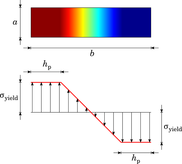
Plastic zone penetration in a rectangular cross-section beam.
The total moment can be divided into an elastic part, M_e, and a plastic part, M_p, such that:
(3)
where I_\mathrm{e}=\frac{a(b-2h_\mathrm{p})^3}{12} is the elastic core moment of inertia along the z-axis.
Combining the last two expressions, we get the following:
(4)
When an elastic-perfectly plastic beam is unloading from M_\mathrm{ep}, a state of residual stress, \sigma_r, remains in the beam cross section. The beam attempts to recover its initial shape following recovery of elastic bending stress, \sigma_\mathrm{e}. Here, it is assumed that purely elastic unloading occurs after being loaded at M_\mathrm{ep}, corresponding to a state of elastic-plastic stress, \sigma. The residual stresses can be computed from the difference between the elastic-plastic stress and the purely elastic stress — i.e., the stress you would have if plastic behavior was not involved.
(5)
The elastic bending theory gives the recovered elastic stress as:
(6)
Assuming a perfectly plastic behavior, the stress \sigma in the plastic zone (in other terms, \frac{b}{2}-h_\mathrm{p} \le |y| \le \frac{b}{2}) remains constant and equal to \sigma_\mathrm{yield}. Therefore, according to the Equation (5), the residual stresses can be written as:
(7)
In the elastic zone (in other terms, 0 \le |y| \le \frac{b}{2}-h_\mathrm{p}), the beam theory provides the applied stress as:
(8)
Therefore, the residual stress is then deduced as:
(9)
Note that after the external moment has been removed, the beam will still have some permanent displacement due to plastic deformation, but it will also have recovered some of the displacement that was present at the peak load. This springback effect is important when you want to achieve a controlled plastic deformation.
When modeling the beam in 2D, we could choose a plane stress assumption taking Poisson’s ratio, \nu=0, to match with the 1D beam theory, which does not account for the Poisson effect. In COMSOL Multiphysics, you can model 2D plane stress by selecting a 2D space dimension and choosing the Solid Mechanics interface.
Computing Residual Stresses in COMSOL Multiphysics
Here, we will show how to use the Solid Mechanics interface in 2D to compute the residual stresses in the beam cross section.
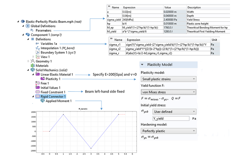
A snapshot of the 2D beam model using the Solid Mechanics interface.
According to the snapshot above, we define variables to evaluate the theoretical residual stresses we worked out in the section above. Those values will be used to compare the computed results with the theoretical ones.
The applied bending moment is ramped progressively. A Plasticity node is added to account for the uniaxial plastic behavior that may occur through the beam thickness. Plastic flow begins once \sigma_x reaches the critical value \sigma_\mathrm{yield}. Any fiber that has reached this value will remain at a constant state of stress during loading.
In the graph below, you can see the stress distribution along the Y-axis of the cross section. The applied bending moment has been computed from Equation (4) for a plastic zone with depth h_\mathrm{p}=\frac{b}{4}=0.01 \ \mathrm{m}. According to the blue curve, COMSOL Multiphysics results match perfectly with this value. The red curve represents the residual stresses after one loading-unloading cycle. It is worth noting that the residual stresses obtained may also be found by subtracting the elastic curve (green) from the elastic-perfectly plastic curve (blue).
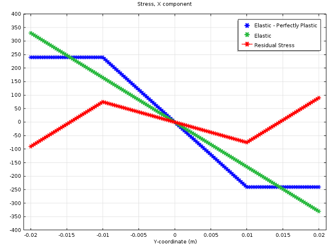
Stress value after elastic-plastic loading, elastic loading, and unloading.
Equations (7) and (9) have been defined as variables and compared to the solution computed in COMSOL Multiphysics. As shown in the previous screenshot, you can create a “switch” using the if() operator, so that the two expressions representing the analytical residual stresses are gathered together in one expression. The next graph shows both analytical and computed residual stresses after two loading-unloading cycles.
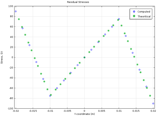
Analytical vs. computed residual stresses.
COMSOL Multiphysics enables you to model the hysteresis cycle of a given material. In the case of perfectly plastic behavior, as depicted below, the second load cycle already provides a stable stress-strain response that is representative of each consecutive load cycle. For instance, you can use these load cycles to carry out a fatigue analysis.
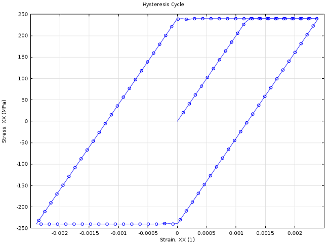
Hysteresis behavior after three loading-unloading cycles.
Last but not least, let’s find out how strain-hardening behavior influences residual stresses and loading-unloading cycles. So far, we have been dealing with a perfectly plastic material. The yield stress remains constant, no matter the number of cycles or whether a tensile or a compressive is applied. Equation (5) is only valid as long as reverse yielding does not occur. Since reverse plastic deformation during unloading has a negative effect on the performance, it is quite important to figure out under which condition reverse yielding is likely to occur.
A ductile material that is subjected to an increasing stress in one direction (in tension, for instance) and then unloaded, will behave differently when loaded in the reverse direction. It is found that the compressive yield stress is now lower than that measured in tension. This is called the Bauschinger effect. Similarly, an initial compression provides a lowered tensile yield stress. The figure below displays this effect over two stress cycles:
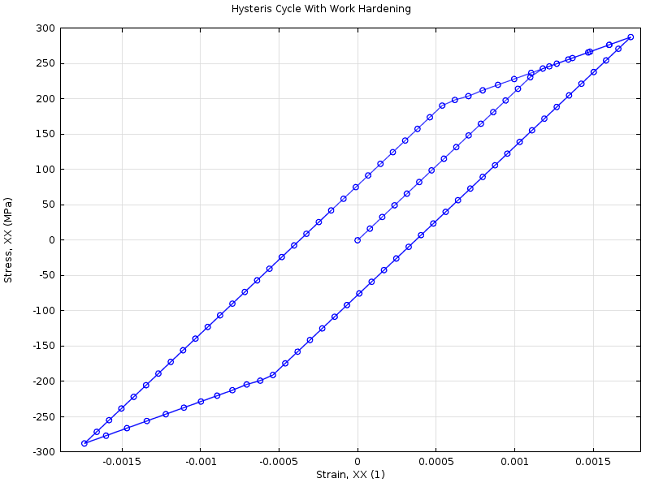
Hysteresis behavior with kinematic strain hardening.
Now, let’s move on to a more sophisticated mechanical process in which residual stresses are of great importance: the sheet metal forming process.
Die Metal Forming
Die forming is a widespread sheet metal forming manufacturing process. The workpiece, usually a metal sheet, is permanently reshaped around a die through plastic deformation by forming and drawing processes. A blankholder applies pressure to the blank, leading the metal sheet to flow against the die.
In order to avoid cracks, tears, wrinkles, and too much thinning and stretching, you can turn to simulations. They can also be useful to estimate and overcome the springback phenomenon. This refers to how the workpiece will attempt to recover its initial shape once the forming process is done and the forming tools are removed. Springback can lead the formed blank to reach an unexpected state of warping. To cope with this effect, the sheet can be over-bent. Thus, the die, punch, and blankholder must be manufactured not only to match the actual shape of the object, but also to allow for springback.
In this study, the sheet is made of aluminum. A Hill’s orthotropic elastoplastic material model with isotropic hardening is used to characterize the plastic deformation. It has been observed that metal sheets in deep drawing process no longer behave isotropically. There tends to be less plastic deformation through the thickness. Therefore, in die forming and deep drawing of sheets, we need a kind of anisotropy where the sheet is isotropic in-plane and has an increased strength in the perpendicular direction, called transverse isotropy.
Below, we have illustrated the forming tools that are used in the process.
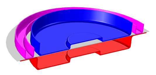
Forming tools: The die is shown in red, punch in blue, blankholder in pink, and the blank in gray.
As mentioned above, simulations can allow for handling several tasks that need to be taken into account whenever such a mechanical process is worked out. For instance, optimization of the corner radius of both the die and the punch can be carried out properly to prevent tearing of the metal sheet. It may also be useful to carry out simulations in order to get the clearance that is needed between the punch and the die, to avoid shearing or cutting of the metal blank.
One of the most challenging aspects is to figure out how much of the metal sheet should be over-bent. When the sheet has been formed, the residual stresses cause the material to spring back towards its initial position, so the sheet must be over-bent to achieve the desired bend angle. Therefore, you have to properly model residual stresses as not to over- or underestimate the springback phenomenon.
The two animations below show the sheet metal forming as well as the springback of the metal blank.
Representation in the RZ-plane of the spingback phenomena.
Simulation of sheet metal forming.
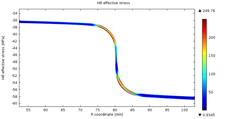
When subjecting the structure to other mechanical loads, the superposition of the residual stresses can reduce the reliability of the structure or even cause irreversible damages. Therefore, the residual stresses must be released as much as possible or be managed so that the structure can withstand the external loads that may be applied. The plot below shows the Hill effective residual stresses that remain around the bend regions after the deep-drawn cup process.
Conclusion and Further Reading
Today, we studied residual stresses in structural mechanics. We introduced a conventional definition, which was first applied to a bending beam example. We simulated this bending example using COMSOL Multiphysics and compared our results to the analytical solution from the beam theory. Then, we explored the importance of the residual stresses in a sheet metal forming example. We saw that any mechanical process induces residual stresses and particular care must be given to release them properly or, at least, be certain that they will not cause any damage.
Learn more about the related products:


Comments (8)
jpoday
June 5, 2014I’d love to see the model file of the die forming.
Jiang Fan
June 6, 2014It would be appreciated if the model of the hysteresis cycle can be shared.
Fabio Bocchi
June 6, 2014 COMSOL EmployeeHi Joseph,
The sheet metal forming model will be available soon in the model gallery. Once the model is live, the link will be added to the blog post content.
Thanks,
Fabio
Fabio Bocchi
June 11, 2014 COMSOL EmployeeHi Jiang,
Thanks for taking out the time to read this blog. If you are interested in the Plastic Beam model and the hysteresis cycle, you may request a copy from your sales representative. (It is not a fully documented and downloadable model.)
Feel free to get back to us for more information.
Thanks,
Fabio
MANISH KUMAR DWIVEDI
November 1, 2015Hi Fabio,
I am a student and currently working on similar residual stresses problem but under thermal loading unloading. Since i am new in comsol i am facing a lot of problem specially in getting residual stresses curve. I request you to please help me out.
Waiting for your reply.
Thanks,
Manish
Fabio Bocchi
November 1, 2015 COMSOL EmployeeHi Manish,
For any technical question, please contact our technical support team at support@comsol.com with all relevant details about what you want to carry out.
Thanks,
Fabio Bocchi
Manish Kumar Dwivedi
December 2, 2015Hi Fabio,
i just want to know what are the x-axis and Y-axis data has been taken to plot the residual stress curve.
IA Palani
April 20, 2016How to make theses animations.. is there a possibility for making such amimations in the COMSOL 5.1.