
Cars have to exist in a variety of environmental conditions. They need to handle environmental changes such as temperature fluctuations. Therefore, it is important to create parts that can handle these conditions. An investigation into the functionality of an inductive position sensor was presented during the COMSOL Conference 2014 in Cambridge.
A Position Sensor for All Conditions
Imagine that you’re driving in the desert. As night falls, the temperature falls with it. You slow down and shift into park, stopping the car at your destination.
When you shifted gears, the car sensed it and reacted properly. For this to happen, parts like automatic gear shifters need to function correctly. A device called a position sensor is used in automatic gear shifter modules and in other parts of cars, such as seat position adjusters. These position sensors need to work well in the varied environments in which cars operate.
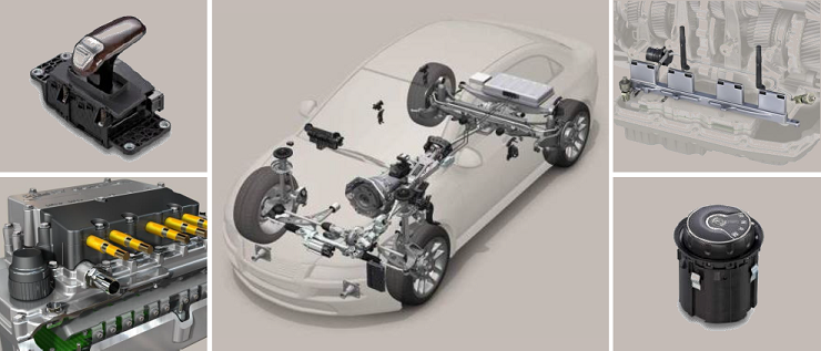
Some uses of position sensors in cars. Image by A. K. Palit, and taken from his COMSOL Conference 2014 Cambridge presentation.
A researcher from Lemfoerder Electronic GmbH (ZF-Friedrichshafen AG. Group) in Germany talked about his simulation of an inductive position sensor at the COMSOL Conference 2014 in Cambridge. He chose to simulate a non-contact inductive position sensor because of its temperature stability and low cost. The typically used Hall sensors are inferior in these aspects since temperature changes alter their performance and they are not a cheap option.
Designing the Inductive Position Sensor Using Finite Element Tools
In order to analyze the workings of an inductive position sensor, the researcher used COMSOL Multiphysics finite element analysis (FEA) software to create a frequency-domain model of a planar inductive coil.

An image depicting an inductive position sensor, with the red shape representing the activator. Image by A. K. Palit, and taken from his COMSOL Conference 2014 Cambridge presentation.
The spiral inductive coils in the model are planar and they form a row on top of the printed circuit board (PCB). The planar coils can have different geometrical shapes: square, rectangular, and circular.
His model also includes an activator (shaped here as a rhombus), which is created from a thin copper plate. The activator rests 0.2 millimeters to 0.3 millimeters above the planar coils. The activator can move, or slide, horizontally over the planar coils. It’s important to note that although the activator can move horizontally, the vertical distance is fixed.
When the copper activator slides close to a planar coil, eddy currents reduce the inductance of that planar coil. In the diagram above, for instance, coils 2, 3, and 4 have a change in inductance due to their placement in relation to the activator. The change in inductance is converted into a corresponding voltage signal that allows you to approximate the activator’s location.
The model that has been described so far focuses on a very limited area of the PCB. This allows for only a small size and number of turns in the planar coils, which can make the sensor incapable of reliable position sensing due to the resulting reduced inductance. To avoid this issue, a model of double-layer planar coil was also created and compared to the single-layer version.
Overall, the position sensor can be visualized as the leaky or loosely coupled primary and secondary windings of a transformer that uses air as the core material.
For more detailed information on the modeling of this device, please check out the paper and presentation.
Analyzing the Results
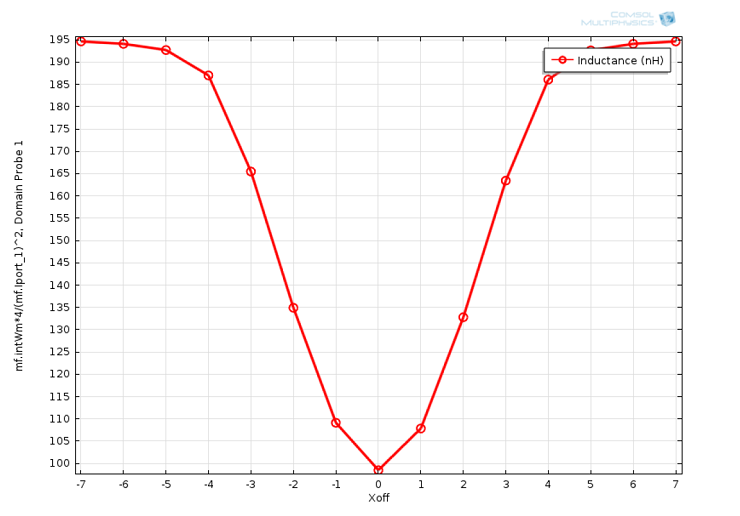
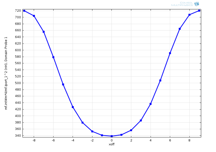
This simulation helped to visualize the real-world functionality of a position sensor by determining the planar coil’s change of inductance in relation to the copper activator’s horizontal movement over the coil. In the position sensor, a change in the horizontal Xoff position correlates to a shift in the physical position of the copper activator. Traditionally, Xoff is a signal to pause or stop a transmission, and in this simulation, it signals the reduction of the planar coil’s inductance. In these graphs, Xoff = 0 indicates the center of the planar coil. At this point, the inductance should be at its lowest value because this Xoff position stops the most inductance. The graphs below visualize how a sliding copper activator with a constant vertical distance produced inductance changes at a frequency of 10 MHz.
Left: The copper activator’s horizontal Xoff position (mm) vs. coil inductance (nH) of a single-layer planar coil. Right: The copper activator’s horizontal Xoff position (mm) vs. coil inductance (nH) of a double-layer planar coil. Images by A. K. Palit, and taken from his COMSOL Conference 2014 Cambridge presentation.
Although both curves look similar, the results have some significant differences. In the graph of a single-layer planar coil, the sliding activator caused an inductance change of around 49% for the coil. However, the double-layer planar coil’s inductance had a higher change of around 53%. The double-layer planar coil also had a much higher inductance value. These are expected results, as a greater coil area is assumed to result in more inductance. The higher amount of inductance (and higher amount of inductance change) in the double-layer planar coil is more likely to be sufficient for reliable position sensing, because the position sensor can better estimate the location of the copper activator.
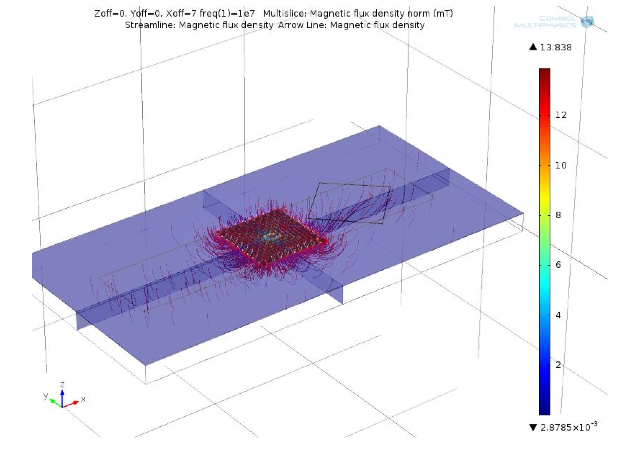
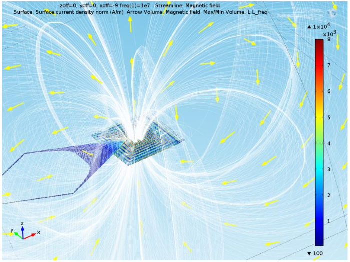
Left: Magnetic flux density norm of a single-layer planar coil. Right: Magnetic flux density norm of a double-layer planar coil. Images by A. K. Palit, and taken from his COMSOL Conference 2014 Cambridge presentation.
The magnetic flux density norm (mT) was also calculated at a frequency of 10 MHz for both the single-layer and double-layer models. By calculating this, we can see the varying magnetic flux in the model’s air core. Although these two images cannot be directly compared, as the double-layer image is zoomed in, the flux density arrows do appear to be more prevalent in the double-layer coil. This indicates that the magnetic field of the double-layer planar coil is greater than the alternative. This is further evidence that a double-layer planar coil will be superior for accurate position sensing.
Taking the Simulation for a Test Drive
Through the modeling of an inductive position sensor and all of the information gained from it, the researcher was able to move forward and create an optimized design that functions in the varied conditions cars experience. This design was optimized by learning what impacts the functionality of an inductive position sensor. He looked into how factors like distance between different elements (namely, the vertical and horizontal location of the activator), geometry, and size affect the efficiency and sensitivity of the inductive sensor. One thing the researcher discovered was that coil inductance could be reduced when the activator is at the center of the planar coil with a vertical distance between the activator and planar coils of 0.2 millimeters or lower. The results of this simulation were directly used to develop an automatic gear shifter module in a German car.
Download the Research
- Read the paper and presentation: “Frequency Response Modeling of Inductive Position Sensor with Finite Element Tools“




Comments (0)