Plate heat exchangers have a larger surface with respect to their volume as compared to a conventional shell and tube design, making for an efficient temperature regulation device. As the name infers, these types of heat exchangers consist of layers of corrugated metal forming channels in between. In order to optimize their performance, you need the flow through the channels to be well-distributed. As you can imagine, the flow is very detailed and modeling it can be computationally demanding, if not restrictive. How can design engineers work around these limitations?
Detailed Flow Simulation in a Heat Exchanger
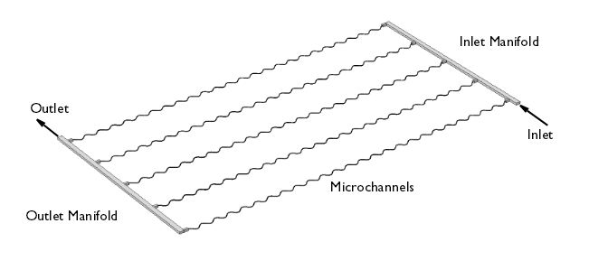
Let’s suppose we have a heat exchanger plate with 2 x 1 x 85 mm inlet and outlet manifolds. The microchannels have a 1 mm cross section. We want to model the detailed flow in the microchannels to investigate their efficiency in the shortest amount of simulation time and using as little memory as possible. Fluid properties are set to water.

A heat exchanger plate model consisting of four microchannels and inlet and outlet manifolds. Using a cosine parametric curve, the microchannels are drawn as edges in the 3D geometry.
Given the problem at hand, this seems like quite the challenge since the mesh requirements for an accurate 3D description of the flow in the microchannels will result in a model with a high number of degrees of freedom. One way we could tackle this is to create a lumped pipe flow model by coupling the equations in the Pipe Flow interface with those in the Laminar Flow interface. The Pipe Flow physics will allow us to solve for the pressure and velocity along the microchannels in 1D by using built-in expressions for the Darcy friction factor. The Laminar Flow physics will use the Navier-Stokes equations in 3D to solve for the pressure and velocity in the manifolds. By using this approach, we will save both memory and time without losing accuracy.
Coupling 1D and 3D Flow
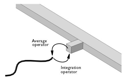
The 1D flow in the microchannels and the 3D flow in the inlet and outlet manifolds need to be coupled at their connections. The manifold inlet flow is set to an average velocity of 5 cm/s. As for the outlets, where they face the microchannel inlets, the pressure is set to be the same as inside the microchannels. You will notice that the channel pressure is only available at the channel inlet point, but we can make it available globally by using an integration point operator. Doing so allows us to apply the pressure value to the manifold’s outlet surface as well. In order to set the flow velocity on the channel inlet to the average velocity across the corresponding manifold outlet boundary, we will use an average boundary operator.

Coupling the Pipe Flow and Laminar Flow physics via Average and Integration operators.
Pressure Drop and Velocity in Heat Exchanger Microchannels
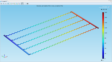
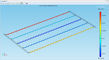
Thanks to the ability to couple 3D and 1D flow, we can solve for the pressure and velocity in the entire heat exchanger’s plate. By plotting the pressure field (left, below), we see that the drop in pressure is mostly due to the microchannels. With a velocity magnitude plot (right, below), we also discover that the heat exchanger will experience reduced efficiency in the central channels where the velocity is lower than the other microchannels. In order to achieve a well-distributed flow in all channels, we would need to improve on the manifold design.

|

|
| Pressure in the heat exchanger plate’s microchannels. | Velocity magnitude showing lower velocity in the central channels. |
Interested in testing this out for yourself? You can download the Convective Flow in a Heat Exchanger Plate model and documentation from the Model Gallery. Note that you will need COMSOL Multiphysics and the Pipe Flow Module to build the model. If you have one of the following additional modules: Batteries & Fuel Cells; Electrodeposition; Chemical Reaction Engineering; Corrosion; CFD; Microfluidics; Subsurface Flow; Heat Transfer; or the Plasma Module; you will be able to use the Laminar Inflow boundary condition as shown in the step-by-step instructions. If you only have the Pipe Flow Module, you can still solve the problem by replacing the inlet condition with a simpler condition.
Further Reading
- Model download: Convective Flow in a Heat Exchanger Plate
- Simulating Plate Heat Exchangers (MEMS)


Comments (0)