
Magnetic gears are the contactless mechanisms for torque-speed conversion using permanent magnets or electromagnets. They are utilized in several renewable energy applications, increasing the speed of wind energy, ocean energy, and flywheel energy storage in order to match the specification of the electromagnetic generator. Unlike their mechanical counterparts, magnetic gears offer inherent overload protection, have high reliability due to frictionless operation, and require no lubrication. Today, we’ll discuss how to simulate magnetic gears in 2D and 3D with COMSOL Multiphysics.
The Construction and Working Principle of Magnetic Gears
A typical magnetic gear consists of three rotors, each with a different number of magnetic pole pairs separated by a small air gap. The ferromagnetic steel poles (middle rotor) modulate the magnetic fields produced by inner and outer rotors and create space harmonics in the air gaps. The modulated magnetic fields via the steel poles interact with the magnetic field on the other side to transmit the torque.
Illustrated in the figure below is the working principle of a typical magnetic gear. For simplicity, we chose the linear magnetic gear configuration. However, the working principle will also be the same for rotating magnetic gears. In this configuration, the model consists of 11 pole pairs on the outer rotor, 4 pole pairs on the inner rotor, and 15 pole pairs in the middle. They are denoted by P_o, P_i, and P_s, respectively.
The 4 pole pairs on the inner rotor produce the magnetic field with a dominant 4th harmonic. This field is then modulated by 15 steel pole pairs to generate a field with a dominant 11th harmonic. The modulated field interacts with the dominant 11th harmonic field that is produced by the outer rotor to transfer torque. This generates the torque, as the field harmonic component from the outer rotor matches with the harmonic component created by the modulated inner rotor field.

A schematic depicting the components of linear magnetic gears. Red arrows represent the magnetization direction of the permanent magnets. The magnetic fields produced by the inner and outer rotors are shown in the blue curves. The air gap between the rotors is not included in the scale (exaggerated).
In order to attain the highest torque density, the number of pole pairs on each of the rotors should satisfy the following relation:
The relation between the pole pairs and the angular speed for all three rotors for maximum torque transmission is given by:
where \omega_i, \omega_o, and \omega_s denote the speed for the inner rotor, outer rotor, and steel poles, respectively. If the middle rotor is kept stationary, the speed and pole pairs relation is given by:
The best combination for P_i, P_s, and P_o is the one with the minimum of torque ripples. Such ripples can be primarily attributed to the cogging torque that is created from the field interaction between the permanent magnet motors and the steel poles. The parameter that is used to minimize the cogging torque is called a cogging factor. It is given by the following equation:
where LCM is a least common multiple. The minimum cogging torque is obtained with C_f = 1. In all of the examples presented here, this condition is satisfied and the ferromagnetic steel pole is kept stationary.
Types of Magnetic Gears
Based on their operations, magnetic gears can be classified into three types: linear magnetic gears (LMGs), coaxial magnetic gears (CMGs), and axial magnetic gears (AMGs). For LMGs and CMGs, the magnetic flux is typically generated radially inward or outward with reference to the shaft axis. However, for AMGs, magnetic flux lines are created parallel to the rotor axis. In this blog post, we will present examples for these three types of magnetic gears using COMSOL Multiphysics.
Coaxial Magnetic Gear
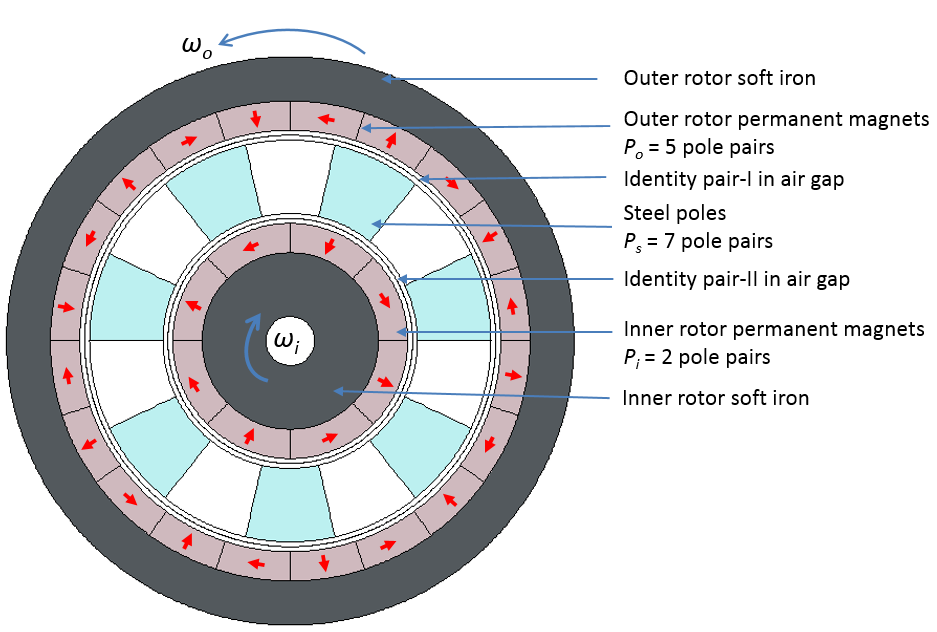
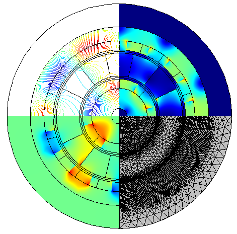
The coaxial magnetic gear consists of three concentric rotors with different pole pairs, as shown in the figure below. The inner rotor is comprised of eight permanent magnets (PMs) and a soft iron yoke that forms an outward flux focusing 2 pole pairs on the rotor. The outer rotor includes 20 PMs and a soft iron yoke that forms an inward flux focusing 5 pole pairs on the rotor. In the inner and outer rotors, the permanent magnets are arranged in a Halbach array configuration. Seven pieces of steel are included in the middle stationary ring, and the same spacing between these pieces forms a stationary rotor with 7 pole pairs.
Left: A schematic of a coaxial magnetic bearing showing the inner rotor, outer rotor, and stationary steel poles. Red arrows represent the magnetization direction of the permanent magnets. The permanent magnets are arranged such that the inner rotor is an outward flux focus and the outer rotor acts as the inward flux focus. Right: Magnetic flux density (norm), magnetic vector potential (Az), radial magnetic flux density (Br), and mesh plot in the 1st to 4th quadrant, respectively.
In the example here, the number of pole pairs are chosen to have the gear ratio of 5:2 and the minimum cogging torque as the cogging factor is unity. In COMSOL Multiphysics, the 2D cross section of the coaxial magnetic gear is modeled using the Rotating Machinery, Magnetic interface in the AC/DC Module. Since the model consists of three separate parts, we must form a union of these parts and finalize the geometry using the Form Assembly so that two separate identity pairs are created in the air-gap regions.
We include the nonlinear material model in the soft iron domains using the B-H/H-B curves. However, the stationary steel pole pieces are modeled as a linear material with a relative permeability of \mu_r=4000. Rotating the inner and outer rotor is possible with the Prescribed Rotational Velocity feature. The axial torque on both rotors is calculated using the Maxwell’s stress tensor method via the Force Calculation feature.
Animation depicting the surface plot of magnetic flux density and the contour plot of magnetic vector potential, A_z. The clockwise and anticlockwise rotation of the outer rotor and inner rotor are shown, respectively, along with the field interaction.
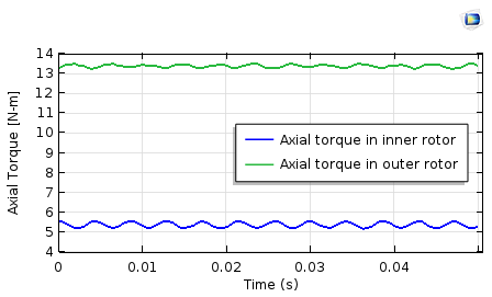
The axial torque profile on the inner and outer rotors. The torque ripple is higher on the inner rotor (less pole pairs).
You can download this example model file from our Application Gallery. Here, you will find the geometry sequence file, COMSOL model file, and a PDF with step-by-step instructions.
Axial Magnetic Gear
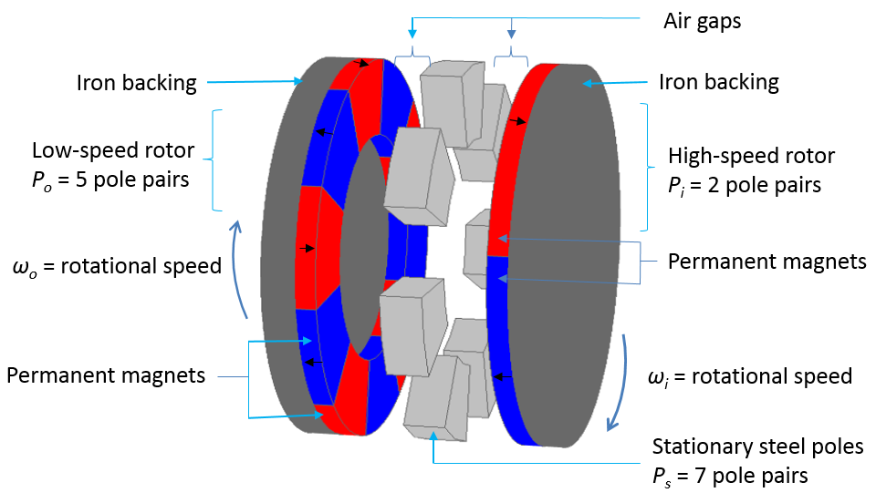
When it comes to the axial magnetic gear, its operating principle is the same as that of the coaxial magnetic gears described above. In this design, the rotors are stacked in an axial direction on top of each other rather than in the radial direction, with a small air-gap separation. Since the surface for magnetic field interaction is large and the length of the three rotors is the same, AMGs provide higher torque densities compared to CMGs. The construction of a typical axial magnetic gear in 3D is depicted in the figure below on the left.
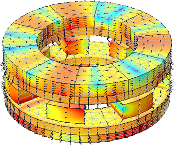
Left: A schematic of an AMG that depicts a low-speed rotor, high-speed rotor, and stationary steel poles. Black arrows represent the magnetization direction of the permanent magnets. Right: Simulation showing the magnetic flux density (surface plot in log scale and arrow surface plot) and a mesh plot.
By downloading the tutorial, you can fully explore all of the details behind the model setup. This particular example includes model files for a stationary study using the parametric sweep and a full 3D time-domain simulation for an axial magnetic gear using the Rotating Machinery, Magnetic interface. Some of the results from the simulation in the stationary and time-domain studies are presented here.
Animation showing the surface and arrow surface plot of the magnetic flux density norm. The clockwise and anticlockwise rotation of the high-speed rotor and low-speed rotor, respectively, are shown, as well as the field interaction.
The torque transmission in magnetic gears can actually be obtained by solving the stationary study for different angular positions between the high-speed and low-speed rotors. Varying the angular position is possible via the parametric sweep in the stationary study. However, for transient simulations, you would need to set up a time-dependent study. Interestingly enough, you will have obtained the identical torque transmission results from these two studies.
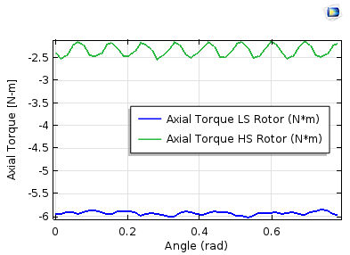
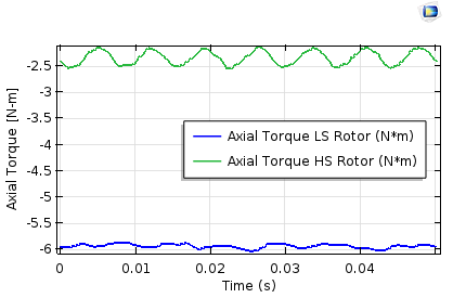
The axial torque profile on the inner and outer rotors. Left: Stationary study and the parametric sweep. Right: Time-dependent study. The torque ripple is higher on the high-speed rotor (less pole pairs).
Linear Magnetic Gear
Linear magnetic gears are utilized in a range of applications. In the oil and gas industry, for instance, they provide gearing for wellbore drilling motors, converting high speed to high torque that is necessary for drilling. Such gears are also integrated with linear synchronous machines for free-piston generators in electric vehicles, while generating wave electricity for wave energy applications.
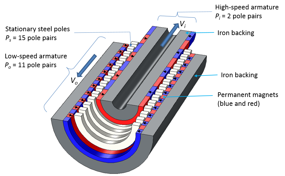
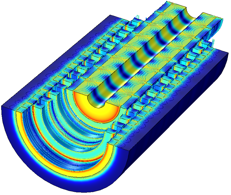
A typical linear magnetic gear construction is shown in the following figure. The gear consists of three rotors with two linearly moving armatures (also called rotors), with stationary steel poles in between. Since the geometry is symmetric about the azimuthal direction, we can solve it using the 2D axisymmetric geometry. In the example presented here, we assume that all of the rotors have the same length and that they are infinitely long in the direction of motion. This condition means that we only need to model a sector of the geometry.
The model is set up in COMSOL Multiphysics using the Magnetic Fields and Moving Mesh interfaces. Because there is no built-in periodic boundary condition for linear periodicity, we create a customized periodic boundary condition for both low- and high-speed armatures with the General Extrusion operator. For a related example, take a look at this previous blog post.
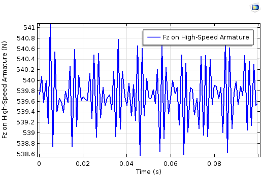
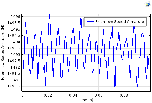
To compute the electromagnetic force coupling between the high-speed and low-speed armatures, we utilize a time-domain simulation. You can download this model file and its associated documentation from the Application Gallery.
Left: Construction of an LMG showing the low-speed armature, high-speed armature, and stationary steel poles. Black arrows represent the magnetization direction of the permanent magnets. Right: Magnetic flux density norm (surface plot) and contour plot of magnetic flux density. The radial component is shown.
The z-component of electromagnetic force on the high-speed armature (left) and the low-speed armature (right).
Animation depicting the surface plot of the magnetic flux density norm and contour plot of the radial component of magnetic flux density. The linear motion of both the high- and low-speed armatures, as well as the field interaction, are shown.
Summary
In today’s blog post, we have presented the major types of magnetic gears that you can model with COMSOL Multiphysics and the interfaces available in the AC/DC Module. Further, we demonstrated the comparison of torque transmission between rotors using stationary and time-dependent studies.
For coaxial and axial configurations, you can directly set up the model using the Rotating Machinery, Magnetic interface. However, for linear magnetic gears, you need to couple the Magnetic Fields interface with the Moving Mesh interface and customize the linear periodic conditions.
Additional Resources for Modeling Magnetic Gears in COMSOL Multiphysics
- Ready to try out our example models yourself? Download them here:
- Learn more about the general guidelines for modeling rotating machines in COMSOL Multiphysics with these blog posts:
- Browse other blog posts featured in our Electromagnetic Device series
- Want to start modeling magnetic gears in COMSOL Multiphysics or have additional questions on your current modeling processes? Please contact us




Comments (4)
Trevor Munroe
May 4, 2016Excellent blog on magnetic gears, Nirmal. For your information, to complement your work on axial gear, there is a good paper on axial magnetic coupling which includes COMSOL modeling results versus experimental results. The reference is as follow: “Experimental and Theoretical Analyses of Axial Magnetic Coupling Under Steady-State and Transient Operations,” by Thierry Lubin, Smail Mezani, and Abderrezak Rezzoug. Also, Magnetic lead screw is another type of magnetic gear/coupling.
Khalid Al Rawahi
March 19, 2019Hello, it is really a good effort and helpful. i just have a problem with the geometry sequence file, COMSOL model file, I could not find that file. could you please help me with that
Alex Wei
May 12, 2019Hello, thanks for your help. I was studying a kind of axial flux motor and it has important reference value, but I need know more about the details. Could you please provide a COMSOL model file.
Ebenezer Omari Abankwa
November 3, 2023please can I get a pdf document tutorial on step-by-step modeling and analysis of magnetic gear ?thank you !!!