MEMS resonators are microelectromechanical systems primarily used as sensor elements, filters, and frequency elements. Two common actuation methods for MEMS resonators are piezoelectric actuation and electrostatic actuation. In this blog post, we will discuss the modeling of electrostatically actuated MEMS resonators. When modeling such resonators, you will often come across terms such as equilibrium point, pull-in, pull-in voltage, and time harmonic response of a biased resonator. We will explain these phenomena using a simple representation of an actuator.
Principles of Electrostatic Actuation
Electrostatic actuators offer certain advantages, including the use of lithographic techniques for ease of manufacture, as well as the ability to use any conductive material as a resonator.
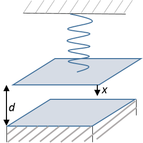
Let’s consider the schematic of an electrostatic actuator consisting of a parallel plate capacitor connected to a mechanical spring, as shown in the diagram below. The electrostatic force acting on the capacitor plate is given by
where W_e is the total stored electrical energy in the system composed of the capacitor with capacitance C and an ideal battery (not shown) supplying the voltage V to the capacitor. Note that this simplistic force expression only applies for a parallel plate capacitor in which one of the plates is rigidly moving up and down while remaining parallel to the fixed plate. It also ignores any edge effects. We will use this simplification to study the behavior of an actuator as it captures the basic concepts of equilibrium and pull-in phenomenon.

Schematic of an electrostatic actuator.
The capacitance can be calculated as C = \epsilon\frac{A}{d-x}, where \epsilon is the permittivity of the dielectric between the parallel plates and A is the area of the plate. The spring represents the elasticity of the moving electrode.
For this 1D analysis, the restoring force in a linear spring is -k x. However, in a general scenario with a large enough displacement, x, the relationship between restoring force and displacement is no longer linear. This is conceptually referred to as large deformation or geometric nonlinearity. We will therefore define the restoring mechanical force in the nonlinear spring as kx + k_1x^2+k_2x^3. You can learn more about geometric nonlinearity in these previous blog posts: “Modeling Linear Elastic Materials — How Difficult Can It Be?” and “What Is Geometric Nonlinearity?”
Solving for Equilibrium
The net force on the capacitor plate is given by
(1)
At equilibrium, the electrostatic force is balanced by the mechanical force so that F = 0. This leads us to the equilibrium equation
(2)
where x_e is the equilibrium displacement.
We can then solve Equation (1) for the equilibrium displacement x_e.
Solving for Pull-In Voltage
A pull-in point is defined as the equilibrium point beyond which the system becomes unstable. Practically, this means that for values of voltage greater than the voltage corresponding to the pull-in point (pull-in voltage), the plates will snap together.
Estimating this pull-in voltage is an important aspect of designing microresonators. To estimate the pull-in voltage, we will need to analyze the stability of an equilibrium point. For simplicity, we will take the case of a linear spring for estimating the pull-in point. As per the theory of stability of an equilibrium point,
&\frac{d F}{d x} |_{x = x_e} < 0\;\;\text{Stable equilibrium} \\
&\frac{d F}{d x} |_{x = x_e} > 0\;\;\text{Unstable equilibrium}
\end{array}
From Equation (2), for the case of a linear spring (small deformation analysis), the voltage at the equilibrium point can be expressed as
(3)
where V_c = \sqrt{\frac{2kd^3}{\epsilon A}}.
Evaluating dF/dx at x = x_e and using Equation (3), we find
Solving the above equation for dF/dx = 0 gives
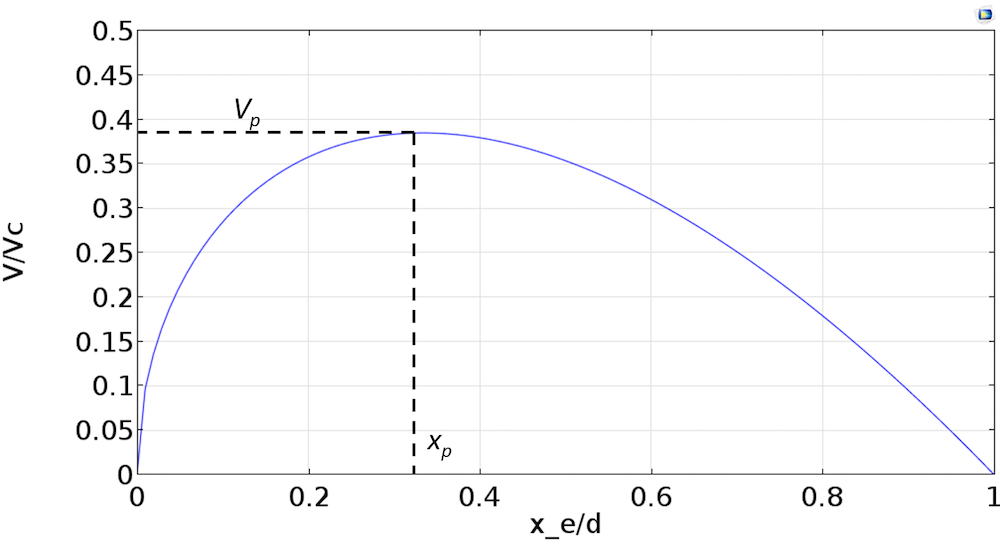
We note that for x_e > x_p, dF/dx > 0 and for x_e < x_p , dF/dx < 0. This indicates that x_p is our pull-in displacement and for values of x_e > x_p, the system becomes unstable. Using Equation (3), we also find that voltage V has a maxima at x_e = x_p = \frac{d}{3}. The plot below shows the relationship between V and x_e.

The pull-in voltage V_p is given by
In the above derivations for pull-in displacement and pull-in voltage, we assume a linear spring. Inclusion of geometric nonlinearity will result in some changes in these values.
Electrostatic Spring Softening
Let’s take a look at the forces on the capacitor plate about an equilibrium point x_e. For a small displacement, x, around the equilibrium point x_e, the total force acting on the parallel plate capacitor is
F &= F_{mechanical} + F_{electrostatic}\\
&= -k(x+x_e)-k_1(x+x_e)^2-k_2(x+x_e)^3 + \frac{1}{2} \frac{\epsilon A}{\left(d -x_e -x\right)^2}V^2
\end{align*}
For a small enough displacement, x, we can perform a series expansion about x_e. Keeping terms to only a second order in x, we get
(4)
F = &-\left(kx_e +k_1x_e^2+k_2x_e^3\right)-\left(kx+k_1x^2+2k_1x_ex+3k_2x_e^2x+3k_2x_ex^2\right) \\
&+\frac{V^2\epsilon A}{2\left(d-x_e\right)^2} \left(1+\frac{2x}{\left(d-x_e\right)}+\frac{3x^2}{\left(d-x_e\right)^2}\right)
\end{align*}
Using Equation (2) to cancel out equilibrium terms, we can rewrite the force as
&F = -k_s(x)x+k_e(x)x,\;\text{where}\\
&k_s(x) = k+2k_1x_e+3k_2x_e^2+k_1x+3k_2x_ex\;\;\text{and}\\
&k_e(x) = \frac{V^2\epsilon A}{2\left(d-x_e\right)^2}\left(\frac{2}{d-x_e}+\frac{3x}{\left(d-x_e\right)^2}\right)
\end{align*}
k_s(x) is the stiffness corresponding to the spring force and k_e(x) is the stiffness corresponding to the electrostatic force. k_e(x) acts in a way to reduce the mechanical stiffness. This is known as the spring softening phenomenon. The value of k_s(x), in the case shown here, increases with an increase in x_e. This is known as stress stiffening. Such an effect is a result of geometric nonlinearity and is discussed in this previous blog post.
Time-Harmonic Response with a DC Bias
In the time-harmonic response analysis of an electrostatic actuator, the actuation voltage can be considered a sum of a DC bias voltage and an AC signal, so that V = V_{DC}+v_{AC}, where v_{AC} = v_0 cos(\omega t) and v_0 is the perturbation amplitude. The electrostatic force is given by
where x_e is the equilibrium point given by solving Equation (2) with V = V_{DC}. We will consider a linear frequency response analysis. For a linear harmonic analysis, the displacements will also be of the form x = Xcos(\omega t+ \phi). Expanding the above equation, we get
We can also expand the term \frac{\epsilon A}{\left(d -x_e -x\right)^2} about the equilibrium point x_e to give
Keeping only the terms to a first order in perturbation amplitude and frequency \omega, we get
The electrostatic force is thus a sum of a DC force and a time-harmonic force at the excitation frequency. Note that in this derivation, we are ignoring the small DC component proportional to v_0^2 and a force component at twice the excitation frequency. We can similarly derive the expression for the mechanical force for linear time-harmonic analysis with a DC bias.
Concluding Remarks on Modeling Microresonators
We have discussed the theory behind the principles of electrostatic actuation using the case of a spring connected to a parallel plate capacitor to analyze the equilibrium, pull-in phenomenon, and time-harmonic response in an electrostatic actuator. We have also discussed the principles of electrostatic spring softening and stress stiffening that occur in an electrostatic actuator.
While the principles discussed in this blog post are important for understanding the fundamentals of an actuator, the expressions derived above cannot be used for an accurate analysis of an actual 3D microresonator. These are based on simplifications and approximations enabling a lumped analysis. Finite element analysis would give us a more accurate picture of the equilibrium, pull-in, and time-harmonic analysis of a microresonator.
In an upcoming blog post, we will take a look at how we can model microresonators using the dedicated Electromechanics physics interface in COMSOL Multiphysics.


Comments (9)
Megan Roberts
May 24, 2016Has the follow up blog post about modeling microresonators with Electromechanics been posted? If so, where is it?
Chandan Kumar
May 26, 2016 COMSOL EmployeeDear Megan, at the moment we have not posted such a blog yet. We do hope to write about it. If you have any related questions, please email your questions to support@comsol.com
Saoni Banerji
July 2, 2016Hi,
I had followed your COMSOL Hands on Workshop on MEMS Simulation which was extremely useful. Following that, I have modelled a MEMS resonator and am trying to plot the variation of capacitance with the applied DC bias using Electromechanics. Starting with a 3D Stationary solver (owing to the perforations in my structure) modelling it in 2D would not estimate the real behavior, I get the following error, despite specifying the Boundary conditions properly.
————————————————————-
Failed to find a solution
Segregated Group 1
system matrix is zero.
Returned solution is not converged.
————————————————————-
Here, there isn’t an option of aattaching the COMSOL file, else I would have attached it for your convenience.
Being a starter of COMSOL, I might be unaware of these issues.
Looking forward to your help,
Thanks in advance,
Kind Regards,
Saoni
Toyab Rahman
May 9, 2017Dear Chandan,
Thanks for your wonderful post. I’m a fan of COMSOL Multiphysics. Actually, I’m working on energy harvesting mechanism where Triboelectric nanogenerator (TENG) is a popular trend on energy harvester field. There are several scientific renowned journals where they used COMSOL Multiphysics for simulating triboelectric properties. However, I haven’t found any post or application or any topic related to triboelectric nanogenerator or even triboelectric properties. I’m just wondering why there is no post or topic from COMSOL Inc.!
Chandan Kumar
May 10, 2017 COMSOL EmployeeDear Toyab,
Thank you for the suggestion. I have noted your suggestion on mathematical modeling of Triboelectric nanogenerator and will be looking into it for a possible COMSOL model in the future. For any specific questions regarding mathematical modeling, please do email us at support@comsol.com.
Best regards,
Chandan
Sri Ram
December 6, 2017Thanks for your post. I’m looking a new application which comes under Electro-mechanics module. can you please give some suggestion to understand the module with proper-way.
Anonymous
December 15, 2017Dear Sri Ram,
Other than the conceptual discussion above, the chapter Theory for the Electromechanics Interface in the MEMS module users guide should be a good read to understand the interface. Then, you would want to review examples related to Electromechanics to get a better sense of how it is applied to modeling. You will find them here: https://www.comsol.com/search/?s=electromechanics&subset=model_gallery
Best regards,
Chandan
zahra elmi
July 31, 2024Hello
Dear Dr. Chandan Kumar
I simulate a capacitor in Electrostatic or electrical currents physics and varying force to calculate the electrical power of the resistor (which is connected to one end of the spring and capacitor). Based on the theory, the electrical power should increase until resonance frequency and after it, the electrical power should decrease. But the electrical power in my model increases for all frequency ranges without decreasing. I am going to fix this problem by analyzing your COMSOL file.
I would appreciate you if I could learn more how to simulate a capacitor in Electrostatics physics by applying varying force and apply the formula in this blog.
Evan Sisler
December 12, 2024 COMSOL EmployeeHi Zahra,
Thank you for your comment! You may find these tutorial models helpful:
https://www.comsol.com/models/acdc-module?q=capacitor&sort=popularity
If you need further assistance, we recommend contacting our Support team using your COMSOL Access account at https://www.comsol.com/support.