Guest blogger Mandar Gadgil of Noumenon Multiphysics discusses modeling phase change in a thermosiphon.
Thermosiphons have been used for keeping houses warm since the 1800s. These devices use central heaters and pipe networks that carry water and steam to different rooms. The cool part (figuratively) is that no pump is needed for fluid transport — convective currents induced by the heater located at the bottom of an installation are enough. Let’s discuss modeling thermosiphons using a “pseudofluid” with temperature-dependent properties.
What Makes Thermosiphons an Efficient Heat Transfer Option?
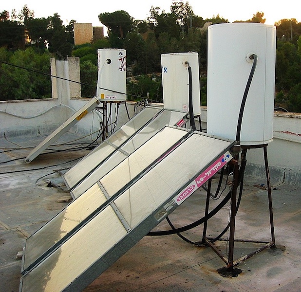
From their initial applications in large-scale heating, thermosiphons have since been used in various industries that rely on efficient heat transfer in small spaces. Today, thermosiphons are found in a wide range of applications: collecting heat from solar panel arrays, heating water and food, cooling IC engines, and even cooling electronic ICs.

An example of a thermosiphon. Image by Gilabrand at English Wikipedia. Licensed under CC BY-SA 3.0, via Wikimedia Commons.
One reason why thermosiphons can be very efficient is that they can operate near the phase change temperature of the transport fluid. This means that the fluid, while carrying heat from point A to point B, uses that heat not only to raise its temperature, but also to change its phase from liquid to vapor.
There are two reasons why phase change in a thermosiphon can be a significant advantage. First, a phase change gives a much greater change in density than a rise in temperature. Fluid transport would be set up much more easily here.
Also, thermosiphon fluids typically need as much heat to change phase as they would to raise the temperature by hundreds of degrees (Celsius). For instance, water has a specific latent heat of vaporization of 2264.7 kJ/kg, whereas the specific heat of water is 4.186 kJ/kgK. This means that the amount of heat absorbed by water, while changing to steam, is 541 times the amount it would need to raise its temperature by 1°C. This means that a lot more heat can be absorbed from a source at a specific temperature if the fluid is changing phase instead of rapidly heating up.
Modeling Phase Change Flow: Common Speed Bumps
The heat transfer from one body to another is proportional to the temperature difference between them. A fluid that stays at a certain temperature during a larger heat transfer would have the advantage of maintaining the same temperature difference for a longer time. This means that the heat transfer rate would stay high for a longer time, instead of dropping as the temperature difference between the heat source and the fluid reduces. However, this very source of efficiency can make modeling the thermosiphon a challenge.
Modeling a flow that involves phase change can be computationally demanding. A usual phase-change fluid flow model involves:
- Two separate domains (one liquid, one vapor)
- An “interface tracking” approach between the two domains that requires a moving mesh on both domains
Another drawback is that this method doesn’t allow topological changes in the interface between the two domains. The creation or merging of bubbles of vapor, for instance, would not be permissible.
Since the interface between the domains is a surface, there would be no modeling of the “slushy”, part-liquid–part-vapor transitional situations. Modeling a thermosiphon with this approach would create an approximation that has a single boundary between the liquid and vapor, which moves as the fluid undergoes a phase change.
A New Approach to Modeling Phase Change with a Single Pseudofluid
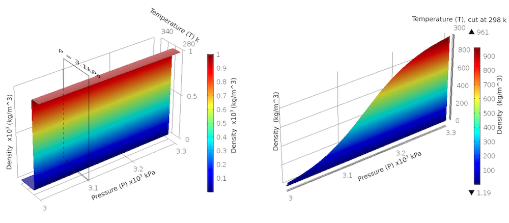
A different approach to modeling this kind of fluid flow problem involves using a single domain of what we’ll call a pseudofluid. This pseudofluid is a material with properties defined as a function of temperature. The properties change from those of the liquid to those of the vapor, over a small region known as the phase transition window. In the figures below, we see how a cross-phase density function is defined to indicate the transition of state from liquid to vapor.

Note: A similar modeling philosophy is used in the Phase Change Material node in the Heat Transfer Module. Though the phase transition could also be modeled using this node, along with the Nonisothermal Flow multiphysics coupling option, the pseudofluid approach allows flexibility in definition of the phase transition function. The pseudofluid material models the phase transition based on two parameters: temperature and pressure. Accurate modeling of the pressure-dependent variation of the density of steam is critical for ensuring mass conservation. The fluid flow and heat transfer equations are solved using the Single Phase, Laminar Flow, and Heat Transfer in Fluids physics nodes available in the COMSOL Multiphysics® software. These two nodes collectively solve the equations for conservation of mass, momentum, and energy.
This modeling approach enables apparent topological changes between phases, since there aren’t any domain boundaries to deal with. This overcomes one of the major approximations of the interface tracking approach. Our solution could now have plenty of pockets of fluid transitioning from one phase to another, which is in line with our everyday observations of fluids brought to a boil, for instance.
There are two approximations inherent in the pseudofluid approach. It doesn’t take surface tension forces into account; so even though topological changes are handled, a big contributing factor in bubble formation during boiling is still left out. Also, phase transition occurs over a small range of temperatures instead of a specific value. The smaller this range is, the more accurate the phase change phenomenon. Ideally, we would choose a range that represents the intermediate slushy stage well. However, a smaller range causes more difficulties in convergence of the solutions.
Validating the Pseudofluid Approach with a Thermosiphon Model
The pseudofluid approach is successful in setting up convection currents and representing the phase change process of the fluid. In the video below, we see a simple vertical container with a fluid being heated, modeled with this approach. Initially, the top portion of the container is filled with vapor, while the bottom portion contains liquid. The container is heated from its bottom surface, and we can see the gradual phase change to convert the entire contents into vapor.
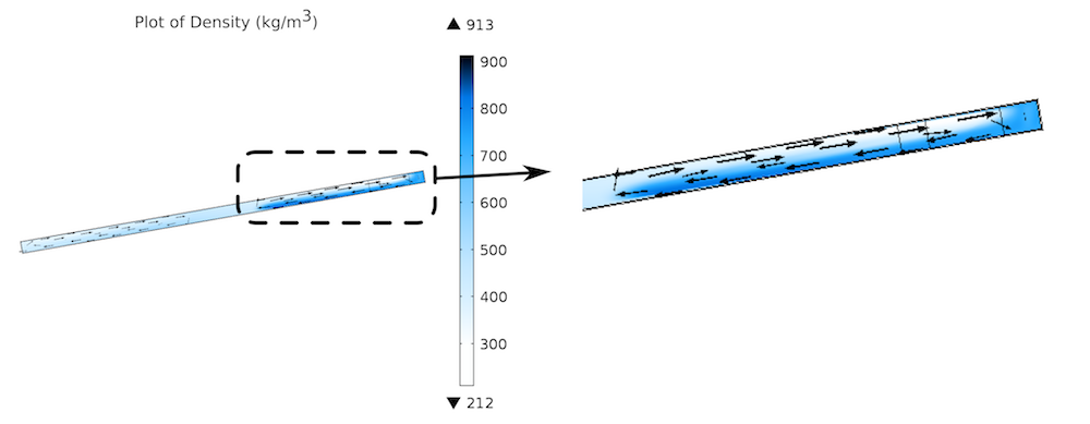
The image below shows the formation of different phases of fluid (represented by their density), as well as the local velocity of the convection currents in a tilted tube, which represents the thermosiphon flask.

Comparing the quantitative performance of the pseudofluid model of the thermosiphon to experimental data — both from in-house experiments and literature (Ref. 1). Steady-state temperatures are compared with data from reference literature at different locations of a vertical thermosiphon. Temperature variation with respect to time is compared with experimental data for a tilted thermosiphon.
The model seems to perform well, and the deviations in performance are within acceptable limits.
Optimizing the Thermosiphon Design
We developed and applied this pseudofluid modeling technique to optimize a real-world thermosiphon application. Once the fluid flow model is set up, the computation time is considerably reduced compared to the interface tracking approach. This frees up computational resources to optimize many other parameters of the thermosiphon.
One objective is to maximize the heat transfer rate of the apparatus. Using a fluid near its phase transition temperature greatly reduces the size of the thermosiphon needed for a certain heat transfer rate.
Another important parameter is the mass of fluid stored in the apparatus. With too much fluid, the heat input needed to vaporize it would be very high. It is even possible that the steady-state heat output would prevent the fluid from vaporizing at all, which would greatly reduce the efficiency of the thermosiphon. Not enough fluid would mean that very little heat would vaporize it. If the heat drawn from the thermosiphon is not high enough, the fluid remains vaporized in the steady state — once again losing the increased efficiency that comes with phase change.
Building on the fluid flow model discussed in this blog post, we can also optimize the thermosiphon’s dimensions, angle of slant, and design of the heat-absorbing surfaces.
Possible Benefits and Limitations of the Pseudofluid Modeling Approach
It is relatively easy to imagine applying the pseudofluid modeling technique to problems concerning fluids that transition between gels and free-flowing liquids. A question worth asking: Can an improved pseudofluid model actually be used as a universal mechanics model? In other words, can this model include the whole spectrum of phase, from brittle solids like rock to free-flowing vapors?
Modeling pseudofluids and phase-transitioning material properties could help in unifying different physics models. A mathematical model that handles these transitions well could even change the way we think about “phases”. Traditional phases may well end up being thought of as approximate descriptions on a continuous spectrum of material states. Although the mathematics to accurately describe these phase changes hasn’t quite been perfected yet, we at Noumenon Multiphysics may have some developments soon!
Note that aside from the two approximations for this approach mentioned earlier, there are some other limitations. This model, though capable of predicting turbulent flows, may become computationally expensive in such scenarios. (For spatial resolution of turbulence, the mesh would need to be refined in the entire domain. For temporal resolution of turbulence, smaller time steps would be required for obtaining converged solutions. So, the number of mesh elements and computational time would both increase. On the other hand, while using a turbulence model along with this pseudofluid material model is also possible, it adds extra equations to the model.) This limitation seems acceptable as far as thermosiphons are concerned, since a turbulent thermosiphon would be greatly inefficient anyways. It is worth noting, however, that different turbulent flow models could be added to the fluid flow model for different applications.
The accuracy of the pseudofluid model depends greatly on the quality of data available about the fluid involved for different conditions of temperature and pressure. Most significantly, the change in density with respect to change in pressure needs to be accurately known to create a useful pseudofluid material model. This is relatively easy for water and steam, but collecting similar data for other fluids may be a more difficult task.
About the Author
Mandar Gadgil is an associate engineer at Noumenon Multiphysics. At Noumenon Multiphysics, Mandar has played an important role in solving numerous challenging problems in modeling and simulation for the engineering industry. He has worked on multiphase, multispecies fluid flow models, models of electric flow for biomedical applications, electromagnetism, fluid-structure interaction, battery modeling, and much more. Mandar has completed his Master of Technology (M.Tech.) with a specialization in modeling and simulation from the Department of Applied Mathematics at the Defence Institute of Advanced Technology, India.
Reference
- F. Bandar, L.C. Wrobel, and H. Jouhara, “Numerical modelling of the temperature distribution in a two-phase closed thermosyphon,” Applied Thermal Engineering, 2013.


Comments (17)
Trevor Munroe
March 12, 2018Could this approach be applied to steam-water ejector?
Mandar Gadgil
March 14, 2018Dear Trevor,
Yes, this approach could be used to model a steam-water ejector.
This approach has been developed to efficiently model any phase-change process. Some modifications could be required based on the actual process details.
Thanks,
Mandar
Priyanshu Goyal
March 14, 2018Can you share the model please?
Sai Phani Kiran Hota
March 16, 2018is the model available in the library for viewing and understanding the type of physics and equation setup used?
Mandar Gadgil
March 19, 2018Dear Priyanshu,
We would be happy to help you in applying the technique to your specific problem.
Please share your email address or please write to us at info@noumenonmp.com
Thanks,
Mandar
MOHAMED YASSIN
May 5, 2020Can you share the model, please?
my email address:-
mohamed.yassin37@yahoo.com
Mandar Gadgil
March 19, 2018Dear Sai,
We would be happy to help you in applying the technique to your specific problem.
Please share your email address or please write to us at info@noumenonmp.com
Thanks,
Mandar
立 王
November 1, 2018Hello, I am doing a two-phase simulation of gas-liquid phase change. As for the phase change problem, I have no idea how to simulate it with comsol. As for your blog, I do not know very well.Can you give me some help
Wen Wen
December 1, 2020Hello,
I want to use Comsol to modeling Heat Pipe, and I looked from your Comsol Blog ‘Modeling Phase Change in a Thermosiphon’, and I’m very interested in your phase change model, it might be used in Heat Pipe modeling as well.
Could you share the model in this blog? It would be grateful.
Thank you very much.
Best regards.
Wen
Repudaman Singh Sandhu
March 31, 2021Dear Sir
I am interested in modeling the evaporation and condensation of Pseudofluid in a closed thermophyson. Can you please share this model in my email address. My email address is repu.sandhu@gmail.com.
Regards
Jiaxi Liao
August 17, 2021Dear Trevor,
Pseudofluid approach is a special way to simulate phase change.Can you share the model please?My Email: lvah@qq.com .Thank you.
Yiya Liao
September 1, 2021Dear Mandar Gadgil,
I am now modeling the phase change of refrigerant in condenser , but I meet big problem about material building and energy balance. So I am very interested in your model. Can you please share this model ? My email address is 40470002H@gapps.ntnu.edu.tw Thank you.
Felix Braun
October 14, 2022Dear Mandar Gadgil,
I’m modelling an heat exchanger with condensating steam for a student work and want to increase the computing time of the modell. I’m trying to use your modelling method but I’m not able to rebuilt your model. Could you send it to my university-email: 2160019@stud.hs-mannheim.de
Thanks & best regards,
Felix
Maria Cruz Navarro
February 15, 2023Dear Mandar Gadgil,
Your pseudofluid approach is an interesting way to simulate phase change.
Can you share the model, please?My Email: mariacruz.navarro@uclm.es
Thank you very much.
Best regards.
Mayaram Sahu
August 29, 2023If you able to share this model, it will be a great help for me. My email id: mayaram.sahu@gmail.com
Yansong Chen
February 6, 2024Could you please share the thermodynamic correlation of the pseudofluid? Did you use the database of COMSOL software or some other resources?
We are very interested in your nice work. Could you please send it to my email: chenys@mail.dlut.edu.cn
ZY G
May 18, 2025Dear Mandar Gadgil,
Your pseudofluid approach is an interesting way to simulate phase change.
Can you please share this model ?
My email address is 1324271126@qq.com
Thank you.