
There are two types of anechoic chambers — acoustic and radio frequency (RF). Here, we explore how periodic structures can be used to help quickly model an RF anechoic chamber by reducing the complexity and computation time of the model.
What Is an Anechoic Chamber?
Anechoic chambers are noise-canceling rooms that are designed to absorb sound or electromagnetic waves. Acoustic anechoic chambers, which typically have noise levels of around 10-20 dBA, can be used to test loudspeakers and the directivity of noise radiation, the sound quality of certain products (such as a Harley-Davidson), as well as to decrease the noise level produced by certain products (washing machines, computer fans, etc.).
First developed during World War II as a way to test aircraft that absorbed or scattered radar signals, RF anechoic chambers are still used today for a variety of different purposes. Like acoustic anechoic chambers, an RF anechoic chamber provides a space where no incident energy waves are present, allowing for devices to be tested without interference. Examples include satellites and the antenna performance of devices such as cell phones, RFID tags, and GPS. When testing on-board aircraft systems, these chambers can be large enough to house the entire aircraft itself.
The image below shows the cones, or pyramidal absorbers, that line the walls, ceiling, and floor of an RF anechoic chamber at the Surface Sensors and Combat Systems Facility at Naval Surface Warfare Center (NSWC) Dahlgren.
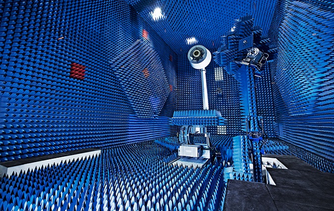
Testing a maritime antenna in an anechoic chamber.
Simulating an RF Anechoic Chamber
You can easily model an RF anechoic chamber using COMSOL Multiphysics and the RF Module with perfectly matched layers and periodic boundary conditions. Let’s explore the one of our models from the Model Gallery: Using the Modeling of Pyramidal Absorbers for an Anechoic Chamber.
In our model example, pyramidal lossy structures (absorbers) are placed in an infinite array. When an incident wave strikes one of the pyramidal structures, many small reflections are created as the electromagnetic wave passes into the pyramid and is reflected into a second pyramid. The absorber is made of radiant-absorbent (RAM) material, which means that as the wave strikes the pyramid, the incident field is partially reflected and partially transmitted into the nearby absorber. Therefore, after many reflections and partial transmissions, the wave’s amplitude is drastically reduced by the time it reaches the base of the pyramid. In the model, we imitate the microwave absorption of a conductive carbon loaded-foam with a conductive material at σ = 0.5 S/m.
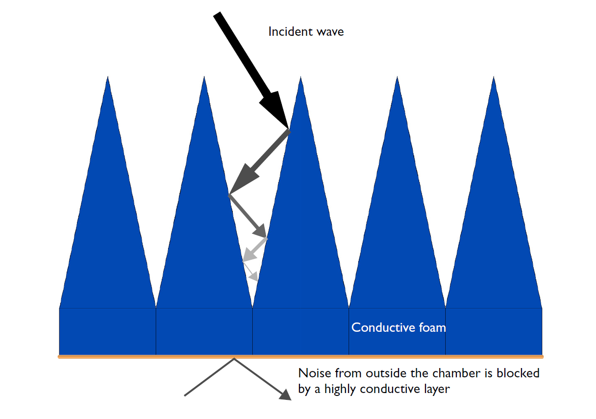
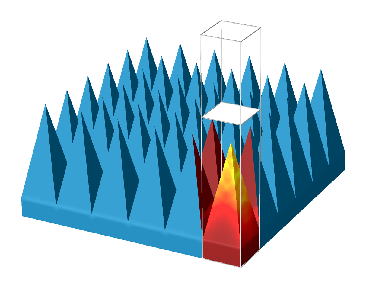
Below, you can see the infinite 2D array of the pyramidal structures. The structure can be modeled using Floquet-periodic boundary conditions on four sides, where one unit of the model contains the pyramidal structure as well as the block beneath it made of the same material. Above the pyramid is a perfectly matched layer (PML) and the space above and between the pyramid and PML is filled with air. At the bottom of the pyramid and block is a layer of highly conductive material that is used to block any noise from outside the chamber (shown in orange in the image above). This layer is modeled as a perfect electric conductor (PEC) in our model.
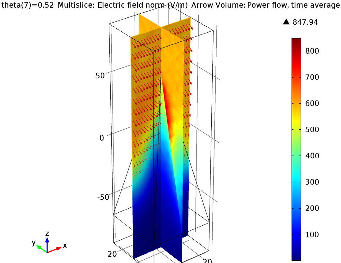
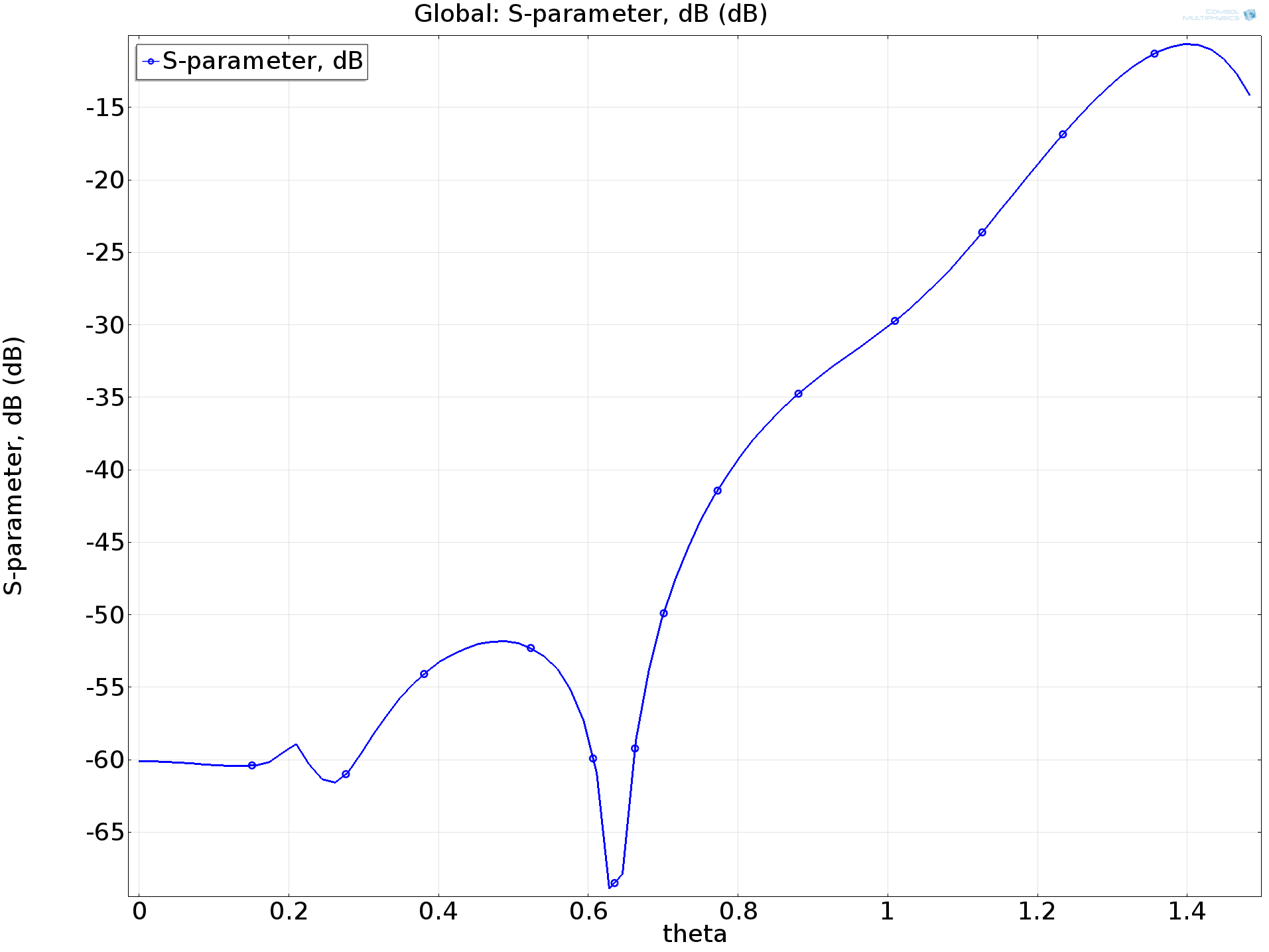
In the plot below on the left, the norm of the electric field and power flow in the model is shown for the case where the angle of incidence on the pyramid is 30°. As we can see, the strength of the incident wave is strong near the tip of the absorber and deceases toward the base of the pyramid. On the right, the graph displays the scattering parameter (S-parameter) for y-axis polarized waves as a function of incident angle.
Model Download
- Download the Modeling of Pyramidal Absorbers for an Anechoic Chamber model to learn how to build it yourself




Comments (0)