
For automotive designers, developing effective evaporative emission control systems in vehicles is an important task. Without these systems, volatile hydrocarbons can escape from a vehicle’s fuel tank, producing air pollution and smog. The COMSOL Multiphysics® software provides the features and functionality needed to model these systems in order to understand their operations and improve their performance. Here’s a look at one research team’s analysis of an evaporative emission control system for bioethanol-blend fuels.
The Impact of Fuel Vapor on the Environment
It’s no secret that the emissions from vehicles can have a profound impact on the environment. As the EPA notes, emissions from transportation resources contribute to environmental problems such as air pollution and smog. This in turn reduces air quality, which results in potential health hazards for humans. Of these emissions, one of the leading contributors to the problem is evaporated fuels.

Fuel vapor emissions from vehicles can have a negative impact on the environment. Image by Reinis Traidas. Licensed under CC BY 2.0, via Flickr Creative Commons.
Over time, the gas within a vehicle’s fuel tank begins to slowly evaporate, releasing volatile compounds into the air. To prevent these compounds from escaping into the atmosphere, vehicles are equipped with evaporative emission control systems — a requirement that first came into effect in the 1970s. These systems feature carbon canisters that adsorb the fuel vapor and funnel it back into the engine when signaled to do so.
Ensuring the effectiveness of evaporative emission control systems is crucial to meeting the required automotive standards. As new types of fuels emerge as alternatives to traditional fossil fuels, it’s important to see how the systems operate with these new components. Combining both of these elements, researchers at Fraunhofer UMSICHT analyzed the operation of an evaporative emission control system based on the composition of a bioethanol-blend fuel.
Modeling Adsorption and Desorption in an Evaporative Emission Control System
The Active Carbon Fuel Emissions Simulator (ACES), part of a funded research project, was used as the foundation for the research team’s model. The ACES features a 2D axisymmetric adsorption model that describes the adsorption and desorption of gaseous fuel components on active carbon. The components within the system are pentane (a gasoline substitute), ethanol, water, and nitrogen.
To implement this model in COMSOL Multiphysics, the researchers from Fraunhofer UMSICHT first set up the mathematical equations used to describe the main parts of the ACES. These parts include:
- Conservation laws for mass
- Species concentrations and heat within the gas phase
- Loading of the adsorbent with adsorbed species mass
- Adsorption isotherms of adsorbed species
- Adsorption kinetics
The researchers used the Chemical Reaction Engineering Module in combination with a Mathematics interface to accomplish this step.
Additional equations relating to the components in the gas phase and energy conservation were implemented via the Transport of Diluted Species in Porous Media interface in the Chemical Reaction Engineering Module and the Heat Transfer in Porous Media interface in the Heat Transfer Module, respectively.
Along with these basic conservation equations, the researchers also addressed the specific adsorption physics. These equations relate to the components’ adsorption isotherms, heat and mass transfer coefficients, and heat conduction and molar diffusion coefficients. To keep the COMSOL Multiphysics model comprehensible and clearly documented, the equations were organized in variable blocks and analytic functions.
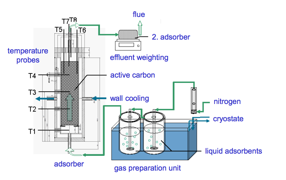
The experimental apparatus for studying breakthrough curves with active carbon and fuel gases. Image by S. Schlüter, E. Schieferstein, T. Hennig, and K. Meller and taken from their COMSOL Conference 2016 Munich presentation.
After setting up their model in COMSOL Multiphysics, the research team’s next step was to run simulations for the loading of a moisturized active carbon bed within a cylindrical adsorber. Previous experiments were performed up to the total loading of active carbon beds with pentane. This was detected by pentane’s breakthrough at the adsorber outlet with an additional weighted “police adsorber”. The simulation studies were designed to replicate the conditions of the experimental studies, recording the thermodynamic conditions within the carbon bed over time.
Comparing Simulation Results with Experimental Data
The first plot below on the left represents the temperature field within the active carbon bed 32 minutes after the adsorption process begins. Depending on adsorption conditions, the temperature can increase up to 130°C as a result of adsorption heat. Here, the temperature rises to about 90°C due to the initial loading of a moisturized active carbon, which has a smaller capacity for hydrocarbons. The plot on the right represents the molar fraction of pentane inside the bed at that same point in time. Close behind the adsorption front, the molar fraction of pentane in the gas phase nears zero. This speaks to the overall efficiency of the adsorber.
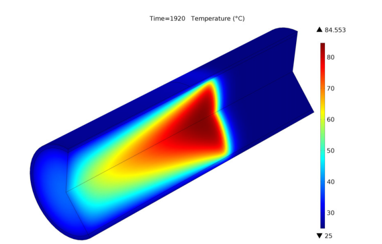
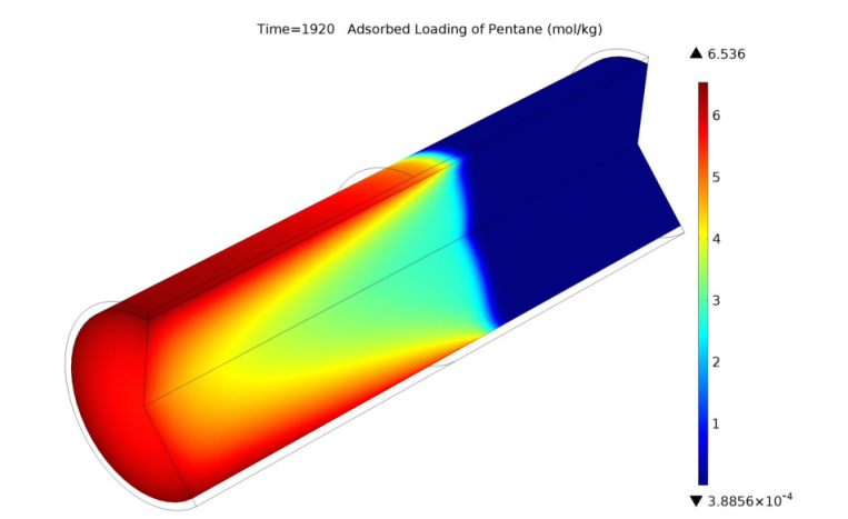
Left: Temperature field plot. Right: Pentane molar fraction field plot. Images by S. Schlüter, E. Schieferstein, T. Hennig, and K. Meller and taken from their COMSOL Conference 2016 Munich paper.
The following plots show the pentane and ethanol adsorbent loading fields after 32 minutes. From the results, it is clear that the distribution of loading within the adsorbent is reflective of the geometry’s temperature field. This is a result of the strong multiphysics coupling between mass transfer, adsorption, and heat transfer — an element that makes COMSOL Multiphysics an optimal choice for modeling this process.
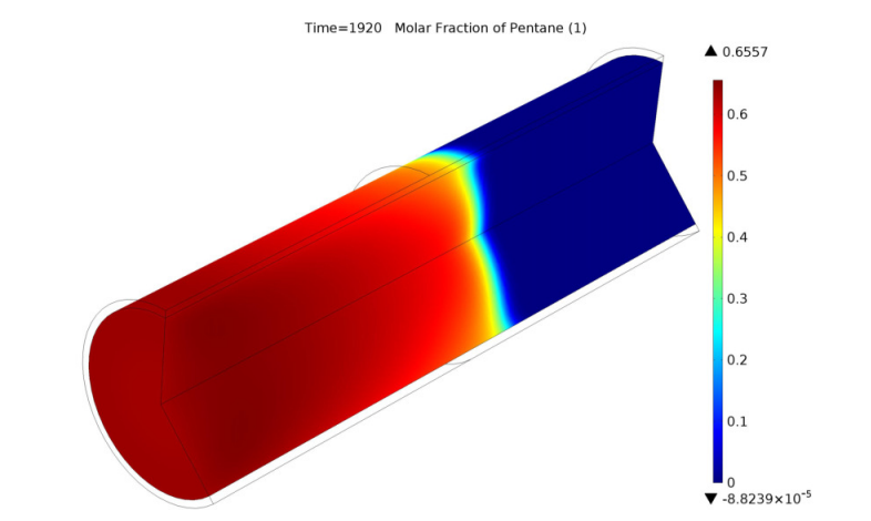
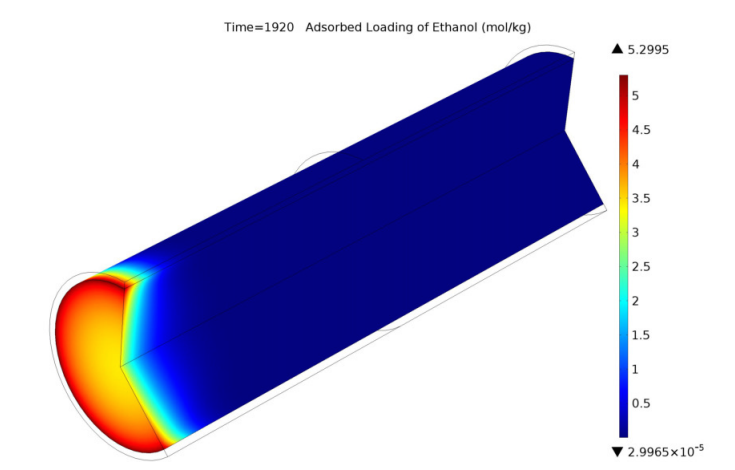
Left: Pentane adsorbent loading field plot. Right: Ethanol adsorbent loading field plot. Images by S. Schlüter, E. Schieferstein, T. Hennig, and K. Meller and taken from their COMSOL Conference 2016 Munich paper.
In the experiments, temperature measurements were obtained by installing probes at particular points inside the bed. To reflect the presence of these probes in the simulation studies, the researchers used the Point Probe functionality. The experimental data and simulation results showed good agreement with regards to:
- Time when the temperature increases at every position
- The rate of increase
- Each probe’s maximum temperature
The simulation seems to underestimate the decrease in temperature with time at every probe position after the initial increase due to the heat of adsorption.
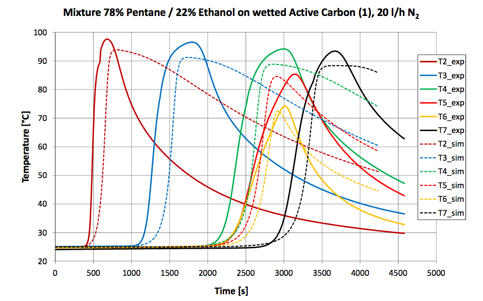
Graph comparing temperature measurements from experiments and simulations. Image by S. Schlüter, E. Schieferstein, T. Hennig, and K. Meller and taken from their COMSOL Conference 2016 Munich paper.
The last part of the simulation analysis looks at the adsorption/desorption cycle. The desorption process takes place directly following an adsorption phase, with air at 20°C. An air inlet is placed at the top of the adsorber. The results show that from one cycle to the next, the carbon bed’s maximum adsorption temperatures become lower. This is due to the adsorber’s imperfect regeneration during the desorption process. Some of the adsorbed gas remains at the lower part of the adsorber and in the adsorption phase that follows, the capacity is lowered. This in turn causes the temperature to become lower. The effect, which becomes stronger from cycle to cycle, is greatly affected by the desorption kinetics that are implemented for the process.
Temperature development in the carbon bed after the second (left) and third (right) adsorption cycles. Images by S. Schlüter, E. Schieferstein, T. Hennig, and K. Meller and taken from their COMSOL Conference 2016 Munich paper.
Better Understand Evaporative Emission Control Systems with Multiphysics Simulation
With the environmental concerns surrounding fuel vapors from vehicles, designing effective evaporative emission control systems is key. But before you can optimize the design, you need to have a good understanding of how this multiphysics system works. As the research from Fraunhofer UMSICHT shows, COMSOL Multiphysics provides you with the features and functionality to do just that — all while giving you the flexibility to see how these designs perform with the fuels of the future.
Explore More Uses of Simulation in Optimizing Automotive Designs
- Download the COMSOL Conference paper: “Simulator for Automotive Evaporative Emissions Restraint Systems“
- See some of the other ways simulation can be used in the automotive industry:


Comments (1)
Sajjad Hussain
July 13, 2019Hi, It is a very good idea. It needs to be operative.