COMSOL Multiphysics version 5.0 introduced users to a new background field feature designed for linearly polarized plane waves. Explore the use of this new feature with an example of polarization-dependent scattering from our Model Gallery.
Going Beyond the Walls
Imagine a situation in which you are seeking the orientation of an object that is not within your sight, perhaps hidden behind a wall. For rescue workers, this is often a particular area of concern. Upon entering a building, workers may hear calls for help but locating their sources can often be a challenge.
Researchers at MIT responded to this issue by developing a portable device that, when pointed at walls, documented any movements occurring on the other side of the wall, making it particularly useful for such emergency situations. By emitting Wi-Fi signals, this device (known as Wi-Vi) tracked movements toward or away from a wall, picking up on shifts as small as a simple step.
In simulation, cases can also arise in which we want to determine a hidden object’s orientation — in a sense, see through walls. With a focus on polarization-dependent scattering, the Detecting the Orientation of a Metallic Cylinder Embedded in a Dielectric Shell model illustrates the use of linearly polarized plane waves in determining the orientation of an object.
The Orientation of a Metallic Cylinder Hidden Inside a Dielectric Shell
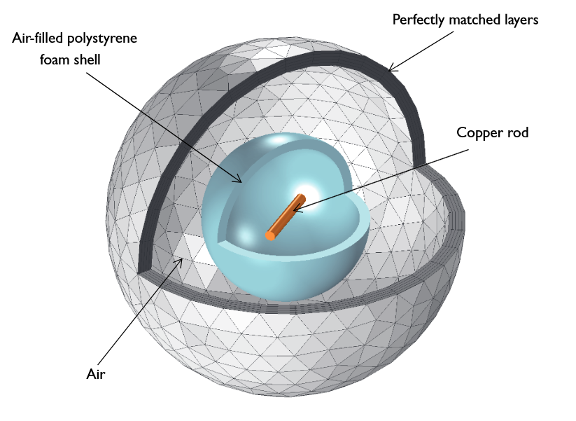
The model consists of a metallic cylindrical rod that is embedded in a polystyrene foam dielectric shell surrounded by air, with the orientation of the rod unknown. Perfectly matched layers (PMLs) are used to enclose the model domain.

A metallic cylinder in a dielectric shell.
The analysis focuses on the detection of the rod for the polarization angle at which the scattered field is greatest. This is accomplished by evaluating the cylindrical object’s polarization-dependent scattered field as well as completing a parametric sweep that is a function of the polarization angle.
A linearly polarized plane wave — a new background wave type in available in COMSOL Multiphysics version 5.0 — is selected for the background field. A linearly polarized plane wave option provides an easy path for defining the background field without having to worry about the validity of a mathematical definition of a plane wave at any arbitrary angle of incidence.
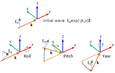
The predefined initial background wave, \mathbf{E}_0=exp(-jk_xx)\mathbf{z}, is transformed by three successive rotations along the roll, pitch, and yaw angles (in that order). If you are interested in flight dynamics, you are likely already familiar with these angular configurations defining a vehicle’s orientation. The image below shows how these parameters are adapted to define the background field.

A linearly polarized background wave.
The roll angle is a right-handed rotation with respect to the +x-direction. The default is 0 rad, corresponding to polarization along the +z-direction. The pitch angle is a right-handed rotation with respect to the +y-direction. In this case, the default is also 0 rad, corresponding to the initial direction of propagation pointing in the +x-direction. The yaw angle is a right-handed rotation with respect to the +z-direction. In the given example model, the direction of a plane wave is defined by the roll angle and the polarization is determined by the yaw angle’s parameterized value.
To model the copper rod, the Impedance boundary condition is applied, with the inner volume taken out of the model domain. A near-field to far-field transformation enables the computation of the rod’s scattered field. Additionally, there is a perfectly matched layer domain outside of the surrounding air that serves as an absorber of the scattered field.
We will skip ahead to the results here, but you can follow the instructions from the Model Gallery to try modeling this concept yourself.
The Results
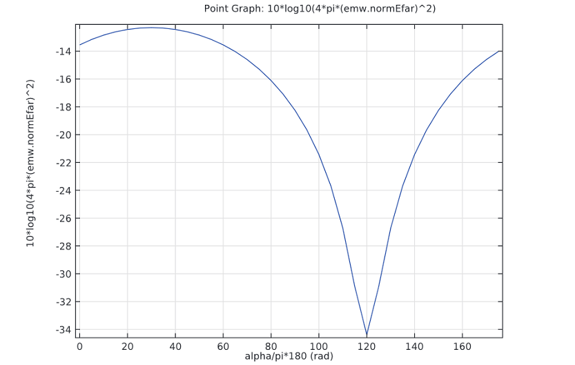
The first plot below depicts the model’s radar cross section in the decibel (dB) scale. The radar cross section is a measurement that refers to an object’s ability to scatter or reflect radio frequency (RF) radiation. When the radar cross section is larger, it indicates that the object can be more easily detected.
From the graph below, we can see that the largest radar cross section occurs at 30º and the lowest at 120º. It is known that the maximum scattering takes place when the polarization and the cylinder are parallel. Thus, we can conclude that the cylinder’s orientation is at 30º.

A graph of the radar cross section. The results show that the maximum radar cross section is at 30º.
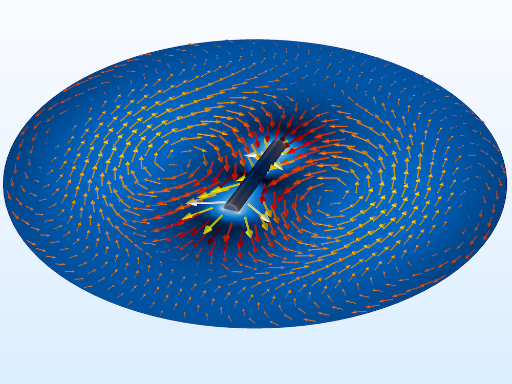
The second plot illustrates the electric field norm in the xy-plane at the highest scattering angle. These results show an electric field that is similar to that of a dipole antenna. An oscillating current is induced along the rod by the background field, with the rod then radiating as a dipole.

A plot showing the electric field norm at the maximum scattering angle. The electric field is similar to a dipole antenna’s electric field.
Try It Yourself
- Download the model: Detecting the Orientation of a Metallic Cylinder Embedded in a Dielectric Shell


Comments (0)