
Imagine you’re on a road trip, cruising down the highway at 60 mph. To maintain this speed, you decide to turn on cruise control. After all, you’re on vacation — why not let the car do the work for you? Whether you go up- or downhill, the car reacts to the change in speed, accelerating or slowing down automatically. This type of process control is thanks to a proportional-integral-derivative (PID) controller. Using simulation, engineers can optimize this kind of control device.
Navigating Process Control
When factoring in variables such as speed, temperature, flow rate, pressure, and more, process engineers can use automatic continuous control to regulate systems. Process control is all about consistency, managing a variety of complex processes through control systems or devices. An early form of automatic process control was the centrifugal governor, which used rotating weights to achieve balance in systems like windmills. Much later, a version of the governor was implemented in steam engines and pendulum governors were applied for speed control.
In the 1920s, engineer Nicolas Minorsky had the idea of using PID as a form of control. He was inspired by watching helmsmen steer ships, manually correcting the course during strong winds and choppy seas. While working on the steering systems on a U.S. battleship, Minorsky began developing a formula for control theory that evolved into the three-term PID control that we know today.

Manual control for ship steering served as the inspiration for PID theory. Image by the United States Navy and in the public domain in the United States, via Wikimedia Commons.
Over time, PID devices have gone through a few iterations (with technology being updated from pneumatic to electronic). A PID controller is an algorithm-based feedback mechanism that continuously calculates the error between a desired setpoint (SP) and a process variable (PV). PID controllers can be applied in mechanisms to automatically course correct a system and keep its PV at a desired SP (like maintaining a certain speed for a moving car).
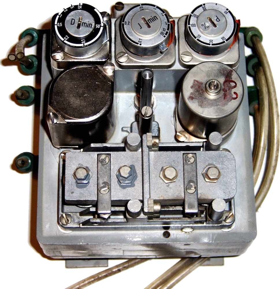
A pneumatic controller with adjustable dials at the top to tune the P, I, and D terms. Image by Snip3r — Own work. Licensed under CC BY-SA 3.0, via Wikimedia Commons.
PID control is commonly used in chemical engineering, helping industrial facilities to automatically and consistently adjust the controlled system via tuning software. For more accurate control in these and other areas, engineers can analyze the process by coupling a PID controller algorithm to their models using the COMSOL Multiphysics® software.
3 Mathematical Terms of PID
The proportional-integral-derivative algorithm consists of three control terms that work together to get the best response. Each term makes a different calculation based on the SP and PV control signals. When the three terms are used together, the device produces a control signal that makes corrections to get back to the desired SP.
Each of the PID terms is an aspect of control that eliminates error, as a calculation for the error’s present, past, and future:
- Proportional: Gives output that is proportional to the value of the current error.
- Integral: Integrates the past values for the error over time to calculate the I factor. This part is necessary in order to bring the error to zero and is therefore almost always included.
- Derivative: Estimates the future rate of error change to make up for any overshoot made by the P and I factors. This part is often turned off because in practical applications, it can amplify the effect of random disturbances and then negatively affect the controller’s stability.
Most often, the combination of PI is used, with PID used occasionally, and more rarely, PD (such as for controlling servomotors). P can also be used by itself.
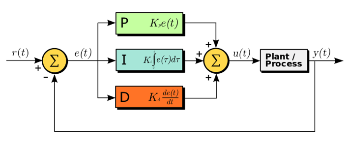
A diagram of a PID controller in a feedback loop, where r(t) is the SP and y(t) is the PV. Image by Arturo Urquizo — Own work. Licensed under CC BY-SA 3.0, via Wikimedia Commons.
Because the three components need to work well together simultaneously within a control system, it can be hard to get the parameters in the PID algorithm to be just right. Using COMSOL Multiphysics, though, you can implement a PID control algorithm to simulate a process control system, enabling you to find the optimal control parameters. Further, the process control mechanism can be coupled to a model in the COMSOL® software, as the following flow mixture example illustrates.
Simulating Process Control with a PID Device
In this model of a combustion chamber, mass transfer and fluid flow with two inlets (a fixed upper inlet and a controlled left inlet) are coupled along with a PID controller. Within the chamber, two streams of gases, each with a different oxygen concentration, are combined. Here, the PV for the flow control is the oxygen concentration at a certain measurement point in the chamber.
The PID controller is used to achieve a desired concentration (SP) of 0.5 mol/m3 at the measurement point. It does so by adjusting the left inlet’s velocity, increasing or decreasing the flow of the gas with the lower oxygen content. The gas with the higher oxygen content enters via the upper inlet at 10 mm/s.
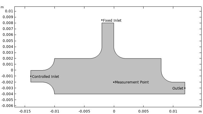
The combustion chamber geometry.
To account for the flow in the chamber, we use the Laminar Flow interface, which calculates the velocity and pressure of the flow. Then, to compute mass balance, the Transport of Diluted Species interface is used, accounting for the convection and diffusion that occurs for the two flow streams and the flux of chemical species. (For details on the boundary conditions for the mass-transport equation, refer to the model documentation.)
The concentration measurement is simulated using the Domain Point Probe feature. The PID algorithm is implemented with user-defined variables and Global Equations. The algorithm calculates the PID-controlled velocity with the following parameters:
- cset — setpoint
- kp — proportional coefficient
- kl— integral coefficient
- kD — derivative coefficient
For this example, we will be focusing on the effect of varying the proportional coefficient (kp).
Evaluating the Simulation Results
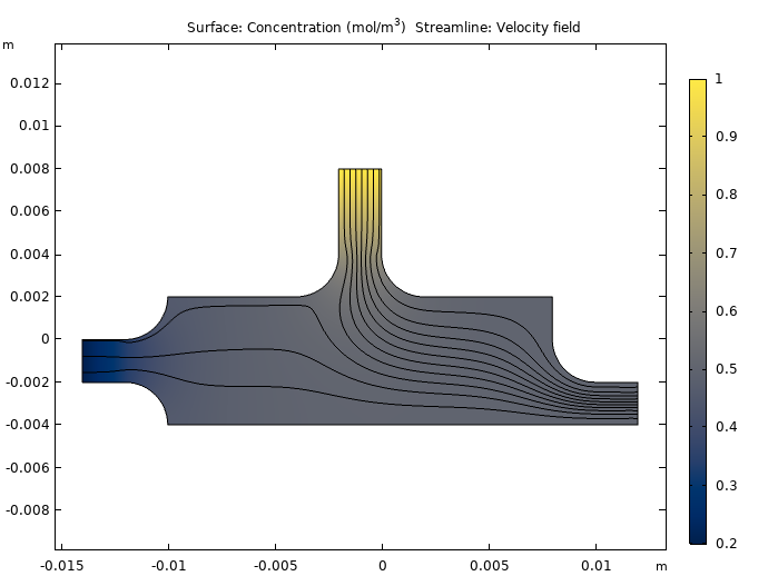
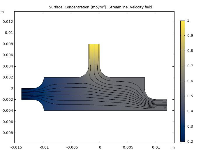
First, within the chamber, let’s take a look at two snapshots of the velocity streamlines and the oxygen concentrations after 0.1 s (left figure) and 1.5 s (right). You can see that at the earlier time, the velocity of the stream entering the controlled inlet is still low, and the sensor is entirely exposed to the stream of highly concentrated oxygen from the top inlet. Then at the later time, in order to lower the concentration, the controller increases the left inlet velocity. Thus, the PID controller is performing as expected, making alterations to maintain the SP. The results also indicate that, as expected, the measured oxygen concentration depends strongly on the flow field.
The concentration of oxygen (color plot) and the velocity field (streamlines) in the combustion chamber after 0.1 (left) and 1.5 s (right).
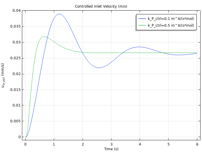
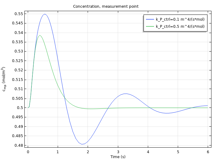
The next figure shows the PID-controlled inlet velocity (left) and concentration at the measurement point (right) over time for two different values of the proportional parameter, kP = 0.5 m4/(mol-s) and kP = 0.1 m4/(mol-s). In both results, the one with the smaller kp value (blue) oscillates more than the one with the higher kp value (green) before stabilizing. Knowing this trend help us optimize the parameter in the PID control algorithm.
PID-controlled inlet velocity (left) and concentration at the measurement point (right) over time for kp = 0.5 m4/(mol-s) (blue) and kP = 0.1 m4/(mol-s) (green).
Going forward, you can apply this same modeling technique to other PID terms in order to continue improving the controller, as well as simulate PID controllers for other systems.
Next Steps
Try the PID controller example by clicking the button below to head to the Application Gallery, where you can download the PDF documentation and the model MPH file.
Learn more about process control in this blog post: Implementing a Simple Temperature Controller with a Component Coupling




Comments (2)
Ivar KJELBERG
June 13, 2019Hi Thomas
Interesting BOG, do you consider adding one on model matrix extraction and some state space controllers, or with a inverse model feed-forward, extracted from a first COMSOL model?
This seems to be possible with the latest matrix extraction features in COMSOL, but I’m lacking some simple examples …
Thanks in advance
Retired, but still having fun COMSOLing 🙂
Ivar
christy chan
July 7, 2020http://www.labideal.com offers quality vacuum components, bellows hose, vacuum fittings and flange, vacuum valves, vacuum pumps, vacuum chambers, vacuum silencer, filters, traps at low price and free shipping all over the world.