
An electromagnetic plunger is an electromechanical device that converts electrical energy into a linear mechanical motion. This motion can be used to move an external load such as closing electromagnetic valves and closing or opening electromagnetic relays. In this blog post, we introduce a procedure to model the behavior and dynamics of an electromagnetic plunger that consists of a multi-turn coil, magnetic core, nonmagnetic guider, and magnetic plunger.
Electromagnetic Actuators Enhance a Variety of Applications
Linear electromagnetic actuators are useful in many industrial applications that require a linear motion, for example, to open or close and push or pull a load. A few common applications for these devices are electromagnetic relays, electromagnetic valves, circuit breakers, and contactors. This technology is also found in the agriculture, construction, automotive, and robotics industries.
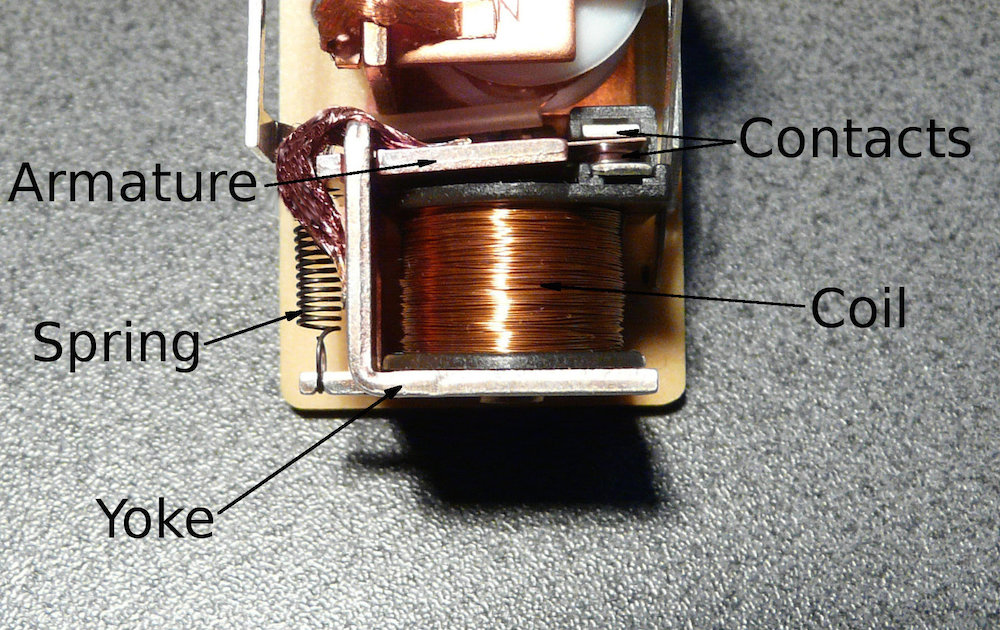
A simple electromagnetic relay with a mechanical spring, coil, armature, and yoke.
With the help of COMSOL Multiphysics, the performance of linear electromagnetic actuators, for example, actuator force and stroke, loading curves, efficiency, and operating frequency can be evaluated as a function of design parameters (size, materials, input voltage and current, etc.). We’ll discuss an example of this in the following section.
Modeling a Linear Electromagnetic Plunger in COMSOL Multiphysics
In this blog post, we consider a simple electromagnetic plunger that consists of a multi-turn coil, magnetic core, nonmagnetic guider, and magnetic plunger. As shown in the images below, these pieces attach to a spring and damper. The transient (rectangular pulse) current passes the solenoid coil, which creates a magnetic field around the magnetic core and plunger. The magnetic field produces an attraction between the two components so that the plunger accelerates and moves upward against the spring. At maximum force, the plunger positions perfectly inside the magnetic core so that it forms the lowest reluctance path for the magnetic flux.
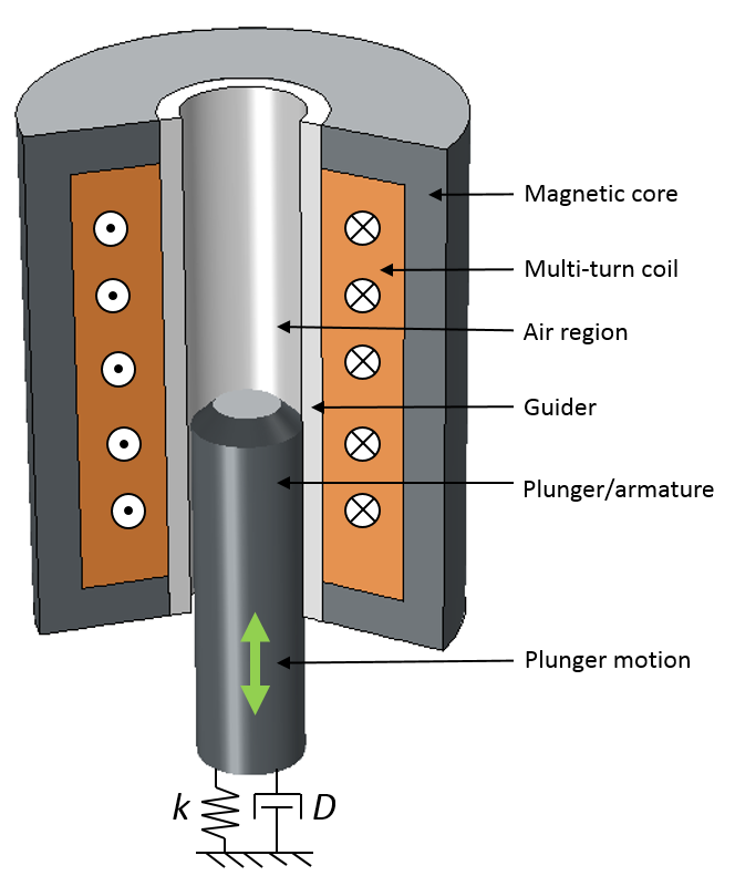
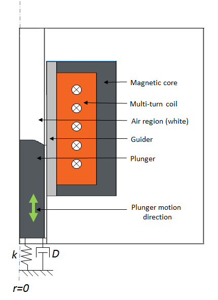
A cut 3D view (left) and a 2D axisymmetric view (right) of an electromagnetic plunger.
For the Electromagnetic Plunger tutorial model, we use a 2D axisymmetric geometry and add the Magnetic Fields, Moving Mesh, and Global ODEs and DAEs interfaces as well as the Time Dependent study type. Next, we define the model parameters under Global Definitions > Parameters, as shown in the screenshot below.
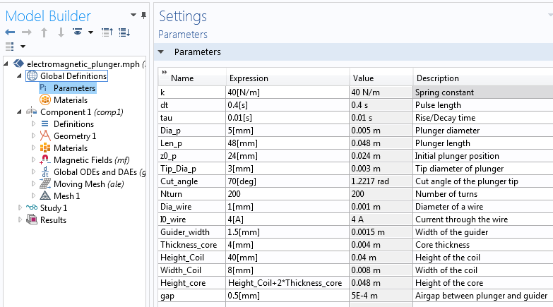
A list of design parameters for the electromagnetic plunger model.
Due to the large translational motion of the plunger, we use sliding mesh to model the motion. For this, we first have to create two separate unions of the stationary and moving parts. We then finalize the geometry using the Form Assembly operation so that the identity pair is automatically created at the interface. For modeling ease, create the selections for the guider, core, coil, plunger, source boundaries, destination boundaries, and force calculation boundaries, as highlighted in the picture below.
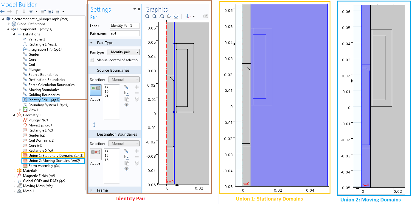
Various selections for stationary domains, moving domains, and identity pairs in the Model Builder.
To compute the plunger’s mass, M, for the dynamic study, we define the integration operator, Integration 1 (intop1). This operator incorporates the volume of the plunger and multiplies it with the assigned material density. In this example, we describe the plunger using the Low Carbon Steel 1002 (mat 3) material. We also define the variable for the electromagnetic force, F_z, and use it to compute the Maxwell stress tensor on the plunger. Before we calculate this, however, we first need to add the Force Calculation feature in the Magnetic Fields interface with the force name force. We explain how to do so in the next section.
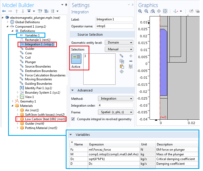
The integration coupling operator and variables.
Modeling the Electromagnetic Fields
We can use the Magnetic Fields interface to simulate the electromagnetic fields in the device. We model the nonlinear materials in both the plunger and the magnetic core by using the Ampère’s Law node with a constitutive relation set to an H-B curve. Similarly, we add the nonlinear H-B curve for the magnetic core region with Soft Iron as the material. Note that while simulating the plunger and core with a single Ampère’s Law node is possible, having two separate Ampère’s Law nodes gives us the freedom to use different constitutive relations, if needed.
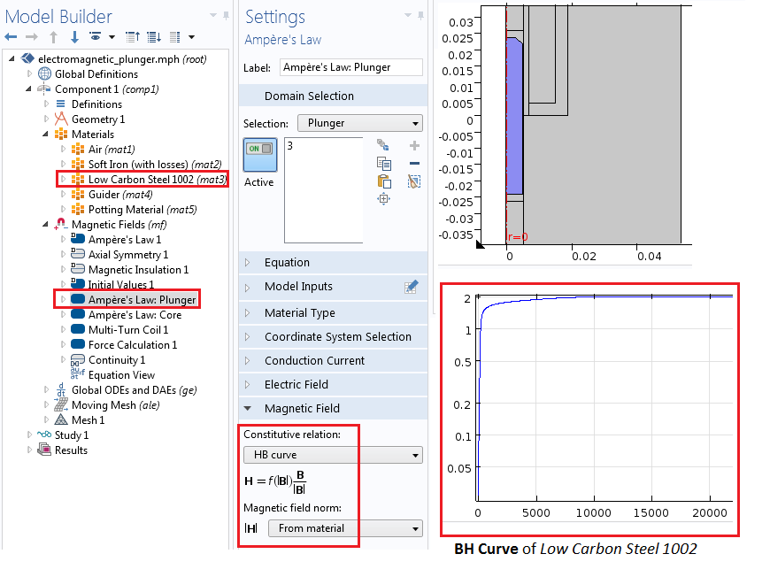
The settings for the Ampère’s Law node, illustrating H-B curve implementation in the nonlinear magnetic plunger region.
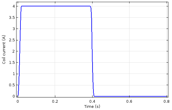
With the Mulit-Turn Coil feature in the Magnetic Fields interface, we create the solenoidal winding. The winding consists of 200 turns (Nturns = 200) for wires with a diameter of 1 mm (Dia_wire = 1 mm) and an electrical conductivity of 6e7 s/m. The current through the coil is a rectangular pulse defined as I_coil = I0_wire*rect1(t[1/s]), where rect1() is a rectangular function defined under Definitions > Rectangle 1. The maximum current is I0_wire = 4 A.
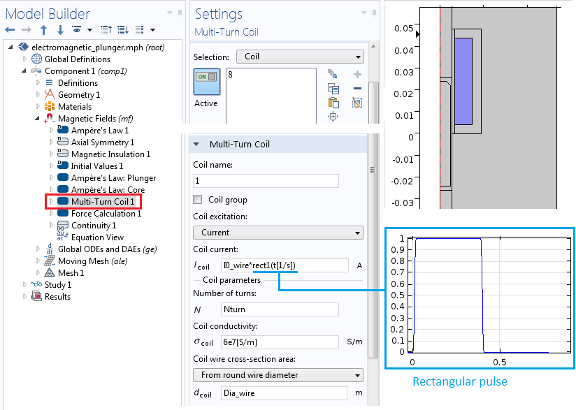
The Multi-Turn Coil feature shows open circuit settings as well as the number of turns, conductivity, and cross-sectional area.
Calculate the electromagnetic force on the plunger by adding the Force Calculation feature to the plunger. This computes the Maxwell stress tensor force acting on the plunger due to the transient current in the plunger. Since the plunger is a magnetic material, the Lorentz force method cannot be used, as it only supports conductive nonmagnetic materials. The Maxwell stress tensor method is sensitive to the mesh and requires a finer mesh on the surface where the Force Calculation feature is added. To calculate the force correctly, you can perform a mesh refinement study.
Next, we’ll add the Continuity boundary condition in the Identity Pair field to couple the magnetic fields between the stationary and moving domains.
Adding Global ODEs and DAEs
The rigid body dynamics of the electromagnetic plunger can be simulated in COMSOL Multiphysics using the Global ODEs and DAEs interface. The equation of motion for the electromagnetic plunger attached to the spring with spring constant, k, and damper with damping coefficient, D, is given by the following equation:
(1)
where p is the position of the plunger in the z direction, v is the velocity, M is the mass of the plunger, and F_z(p,v,t) is the electromagnetic force of the plunger acting against the spring.
The above equation can be rewritten into two separate differential equations for the position and velocity as:
(2)
and
(3)
We implement these equations using the Global ODEs and DAEs interface, where we add two separate global equations, as shown below.
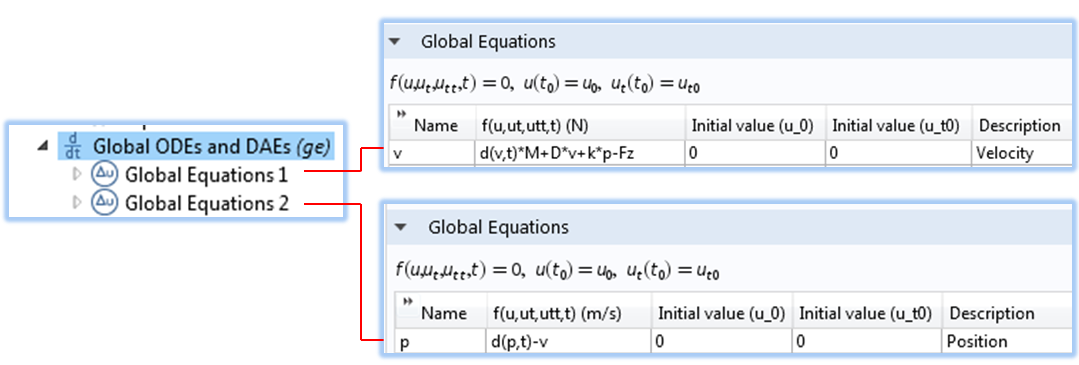
Implementing the differential equations for velocity and position using the Global ODEs and DAEs interface.
Simulating Translational Motion
To model the translational motion of the electromagnetic plunger, we add the Moving Mesh interface. Similar to the modeling technique described in this oscillating magnet tutorial model, we can apply the Moving Mesh interface in only the moving domains (the plunger and air domains on the left side of the identity pair). Three sections partition the air domain to the left of the identity pair to simplify the moving mesh setup. The top and bottom air regions have either a contracting or expanding mesh setup, and the middle region has a fixed mesh that moves according to the prescribed boundary displacement settings.
To fully enclose the plunger, assign a Prescribed Mesh Displacement feature with a deformation equal to the position variable, p, to the boundaries of the middle section. The two vertical boundaries in each of the deforming air regions, found under Guiding Boundaries in the selection list, are constrained in the r direction only. The image below shows the settings for the Moving Mesh interface.
Note: The plunger, along with a small air region surrounding it, is moving. This simplifies the meshing setup for the Moving Mesh interface because this setup allows us to have a mapped mesh in the other two air regions. We will address the more challenging mesh setup in the second part of this blog series.
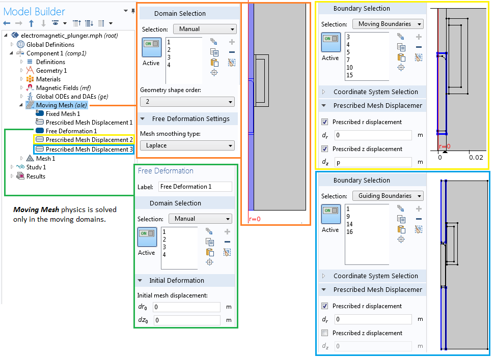
The settings for the Moving Mesh interface.
We assign the stationary domains a fixed mesh, whereas the moving parts use the prescribed deformation in the z direction. The position variable, p, from the Global ODEs and DAEs interface defines the prescribed motion.
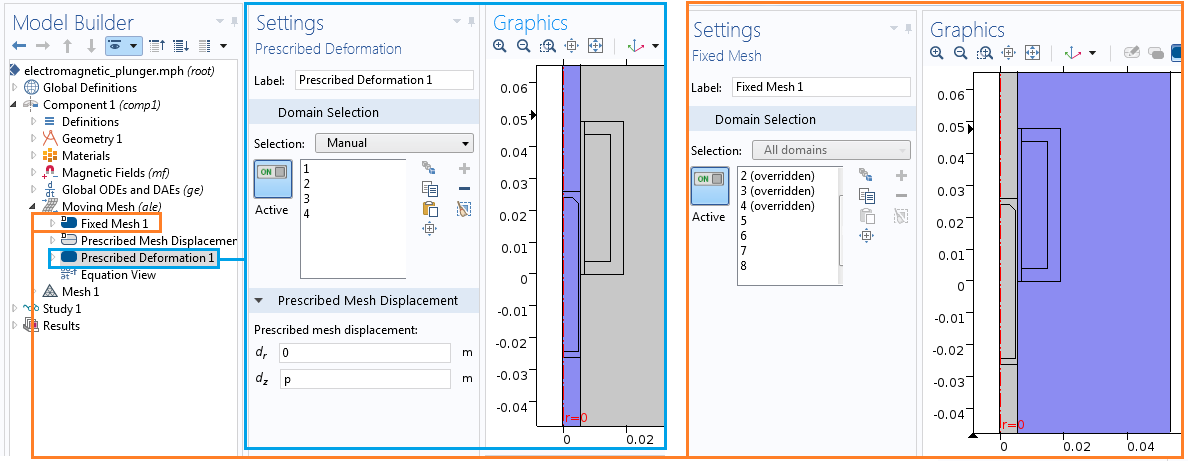
An alternative method for setting up the Moving Mesh interface.
Evaluating the Simulation Results
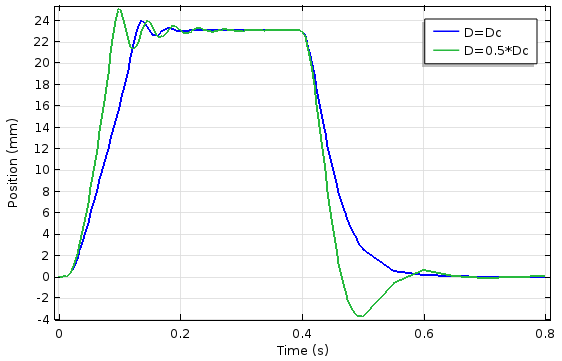
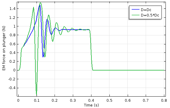
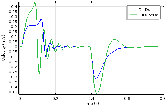
The results of the time-dependent study of the electromagnetic plunger can be seen in the graphs below. We performed the simulation for two different values of the damping coefficient. As expected, the system exhibits more oscillation when the damping coefficient is less than the critical damping coefficient. The rise time of the overshoot, however, is shorter.
The plunger position (left) and electromagnetic force on the plunger (right) as a function of damping coefficient and time.
The plunger velocity as a function of damping coefficient and time (left) and the current through the coil as a function of time (right).
The animation below demonstrates the dynamics of the plunger for the applied transient current in the coil. On the left, we see a 3D visualization of an electromagnetic plunger with the magnetic flux density norm plot, while on the right, we see the corresponding plot for the plunger position and the current through the solenoidal coil.
Concluding Thoughts on Modeling Electromagnetic Plungers and Actuators
In this blog post, we present the modeling steps for linear/translational electromagnetic actuators using three different physics interfaces: Magnetic Fields, Moving Mesh, and Global ODEs and DAEs. We compute the electromagnetic force, plunger position, and velocity by fully coupling the Magnetic Fields interface with the Moving Mesh interface and the differential equations describing the plunger dynamics.
Stay tuned for an upcoming blog post on how to further expand this example to model the dynamics of a plunger with restricted oscillation. We will demonstrate the use of the Events interface to model the contact and release operation of the electromagnetic plunger.
Learn More About How to Model Electromagnetic Devices
- Download the Electromagnetic Plunger tutorial model
- Check out more blog posts on electromagnetic modeling:




Comments (11)
Pitotech Pitotech
June 7, 2016Dear Paudel:
It is useful when using moving mesh.
But I have a problem about why not use the ODE to solve the Laplace smoothing Eq on the blog.
https://www.comsol.com/blogs/model-translational-motion-with-the-deformed-mesh-interfaces.
What’s the difference in these two blog ?
Nirmal Paudel
June 9, 2016 COMSOL EmployeeHi,
The Laplace smoothing equation is one of the built-in method in the Moving Mesh interface. That is exactly what we used in this tutorial example.
Best Regards,
Nirmal
Pavlos Zairis
June 10, 2016Hi Nirmal,
I am trying to simulate the same problem as you describe, but I don’t have the expected results. I am not sure if I define the forces correctly or I should use the form assembly with identity pairs ( I am using the form a union at the moment).
The problem is that the plunger is moving over the stator, which is not possible in reality.
Do you have some advice about that?
Regards,
Pavlos
Trevor Munroe
June 12, 2016Nirmal,
Another good blog. It would be good comparison if you replace the global expression with the Solid Mechanics Physics option in part 2 or a part 3.
Trevor
ahmed mansour
July 9, 2016Hi all
Does anybody knows how to set perfectly matched layer (PML) in boundary condition in electromagnetic wave time domain (teew)
Bridget Cunningham
July 11, 2016 COMSOL EmployeeHi Ahmed,
Thank you for your comment.
For questions related to your modeling, please contact our support team.
Online support center: https://www.comsol.com/support
Email: support@comsol.com
Best,
Bridget
Tapan kumar Mahanta
May 13, 2017Hi Nirmal,
In Geometry section you didn’t created moving boundaries. How it came in Definition sections. Another thing is how you select Source boundaries (17,19,21) and Destination boundaries (14,15,16).
Caty Fairclough
May 30, 2017Hi Tapan,
Thanks for your comment.
For your question, please contact our Support team.
Online Support Center: https://www.comsol.com/support
Email: support@comsol.com
Elias Aad
July 16, 2017Hello,
Is it possible to model the plunger as a permanent magnet ?
So I would like to simulate the same situation however with the plunger being a permanent magnet.
Thank you
Regards
Bridget Cunningham
July 28, 2017 COMSOL EmployeeHi Elias,
Thank you for your comment.
For questions related to your modeling, please contact our Support team.
Online Support Center: https://www.comsol.com/support
Email: support@comsol.com
Prasanna Kumar Routray
February 28, 2024Hi Nirmal, how about the case where the plunger itself is a permanent magnet?