Polymer electrolyte membrane or proton exchange membrane (PEM) fuel cells provide a potentially clean and portable source of power. This is of major interest to the transport industry as well as for power generation at fixed sites. COMSOL Multiphysics is a powerful simulation tool you can use to help understand and overcome PEM fuel cell design and construction challenges.
Mass Transport Analysis of a High-Temperature PEM Fuel Cell
High-temperature PEM fuel cells operate at temperatures above 100°C, unlike their low-temperature counterparts, which operate around 70-80°C. Because of electrochemical reactions that take place in the cell, water is generated on the cathode side. Water may also collect on the anode side if there is water in the hydrogen stream. If the water is allowed to build up in the fuel cell, cell reactions will occur at a lower rate, and ultimately the entire system will be less efficient.
To avoid this, engineers can turn to COMSOL Multiphysics and the Batteries and Fuel Cells Module to investigate their design. They can also study the influence of electrode thickness, porosity, catalyst activity, and pore electrolyte content on the performance of the cell.
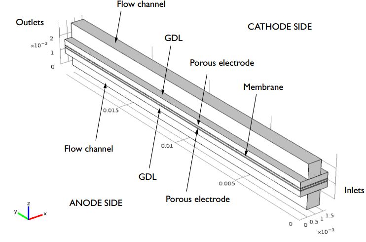
If you want to see an example analysis of the transport of water and reactants and the current density distribution in a high-temperature PEM fuel cell, our Mass Transport Analysis of a High-Temperature PEM Fuel Cell model is a good place to start. This model highlights both anode and cathode mass and momentum transport phenomena in gas diffusion layers (GDLs), flow channels, and the porous catalyst layer. These phenomena are coupled to the reactions in the catalyst layer and the electrochemical currents carried through the GDLs and the membrane itself.

Geometry of a high-temperature PEM fuel cell.
Ohmic Losses and Temperature Distribution in a Passive PEM Fuel Cell
When you’re designing the air side of a passive fuel cell, the objective is to make sure that an even current density and heat profile exist over the cell, which is subject to a range of surrounding temperatures and current loads. Typically, the holes in the cathode current collector plate should be large to provide a good reactant transport to the electrode.
However, the hole-to-solid material ratio may not be too large since the structural rigidity and electrical conductance from the plate, across the gas diffusion layer to the active layer (gas diffusion electrode), will be diminished. If the holes for the air channels are made too large, the path for the conduction of current from the current collector plate to the parts of the active layer just below the center of the holes will become too large and the current will concentrate to the regions that are closer to the electrical contact with the current collector.
The current density will then be higher at these regions, resulting in higher ohmic, concentration, and activation overpotentials. This is also valid in cells with straight and serpentine channels, where the width of the channels have to be optimized.
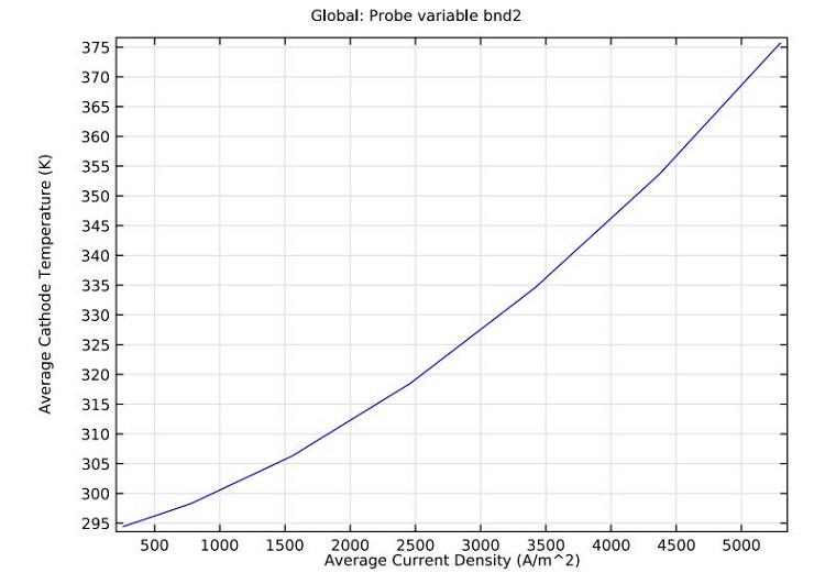
The Ohmic Losses and Temperature Distribution in a Passive PEM Fuel Cell example model illustrates the current density and heat profile over a passive PEM fuel cell.

Cathode average temperature dependence on average current density.
Species Transport in the Gas Diffusion Layers of a PEM
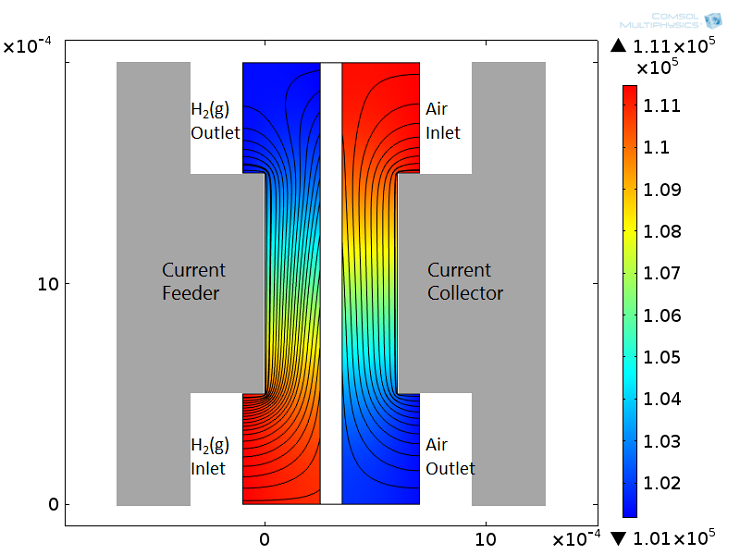
Sometimes, a cell with serpentine flow channels or a cell using interdigitated flow field design may have two adjacent flow channels at different operating pressures. With COMSOL software, engineers can study the detailed mass transport within the GDLs of a PEM fuel cell where this scenario can occur.
The model, Species Transport in the Gas Diffusion Layers of a PEM , depicts how you can combine electrochemical current sources with gas-phase mass transport fluid flow to simulate all physical phenomena controlling a PEM fuel cell’s current-voltage characteristics.

Gas velocity streamlines and pressure field in the anode (hydrogen side) and cathode (air side) porous electrodes.
Fuel Cell with Serpentine Flow Field
The design of a fuel cell flow pattern influences the current distribution, pressure drop, and fuel utilization in the cell. A typical design approach uses serpentine channels to evenly distribute the reacting fluid over the electrode area. The advantage of the serpentine design is that it creates parallel channels of equal length and similar flow resistances for a small inlet manifold. However, this design has its flaws as it may induce unnecessarily high pressure drops.
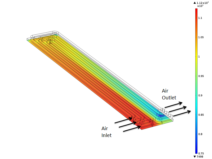
The Fuel Cell with Serpentine Flow Field model is a great example of how you can use COMSOL software to ensure the serpentine design functions properly. The model depicts the cathode air flow and mass transport in three serpentine channels and the corresponding current density in the underlying active layer of a polymer electrolyte fuel cell.

Schematic showing cathode current density.


Comments (3)
Federico Giai Pron
March 1, 2017Hi,
Starting from the first model shown in this review, it is possible to introduce the saturation effect? I’m trying to do it but there are a lot of difficulties in achieving the convergence of the model. If someone has been able to do it, please, can contact me?
Caty Fairclough
March 1, 2017Hi Federico,
Thank you for your comment! For questions related to your modeling, please contact our support team.
Online support center: https://www.comsol.com/support
Email: support@comsol.com
Best,
Caty
Rahul Khandge
May 21, 2020Can I get the Youtube link for this example.