
Small, powerful, and efficient, thermal actuators are a good choice for devices such as thermostats and MEMS. This type of actuator heats up via an applied voltage and deforms in such a way that it “actuates” another component. Thermal actuators involve tightly coupled electrical, thermal, and structural phenomena that affect device performance and must be accounted for. Using the COMSOL® software, you can gain insight into these multiphysics interactions and optimize thermal actuator designs.
Thermal Actuators: Small Devices with a Large Impact
Thermal actuators, like heating circuits, work through Joule heating, which involves several effects:
- An electric current flows through the actuator
- The material’s resistance to the current generates heat
- The heat results in thermal expansion, which displaces the actuator and could change its electrical resistance
Unlike with heating circuits, deformation is a desired effect in thermal actuators, as this is what enables their function.
Compared to other types of actuators, thermal actuators provide a number of advantages. For instance, they’re often more efficient than, say, comb drives and other electrostatic actuators, as they don’t need a high operating voltage to work. This makes them useful for devices like thermostats and safety shut offs. Further, thermal actuators are a good choice for MEMS thanks to their small size; large force generation; and, of course, ability to convert electrical energy into motion at the microscale.
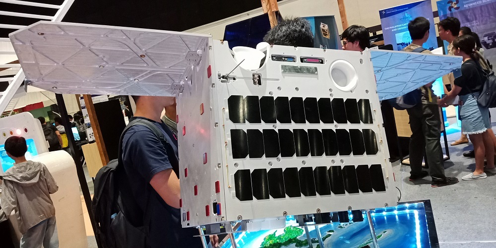
Microsatellites like this one can use thermal microactuators for active thermal control. Image by RoyKabanlit — Own work. Licensed under CC BY-SA 4.0, via Wikimedia Commons.
Some uses of thermal actuators (or microactuators, in this case) include:
- Enabling active thermal control for microsatellites
- Driving micromirrors (e.g., as scanners)
- Actuating micropumps in microfluidic systems
- Providing precise movement in medical devices
- Controlling RF tunable filters
The design of a thermal actuator is often more complicated than other actuators. They usually have to be created with the intended purpose in mind, as the heat must be high enough to cause thermal expansion, but not hot enough to cause permanent deformation. Using multiphysics simulation, engineers can analyze thermal actuator designs for real-world use. Let’s take a look at a thermal microactuator model built using the COMSOL Multiphysics® software. (Note: The model also requires either the MEMS Module or Structural Mechanics Module.)
Modeling Joule Heating in a Thermal Microactuator with the COMSOL® Software
The example consists of a substrate and a microactuator. The microactuator has two hot arms; one cold arm; an anchor at the end of each arm (fixed in place); as well as three dimples, which are able to move back and forth along the xy-plane. For most of these surfaces, a Heat Flux boundary condition is used to represent how convection carries heat away from the device to the surrounding air. If needed for accuracy, the model can include radiative cooling, but this effect is not included in this example. (Learn more about modeling heat radiation in previous blog posts on underground cables and utility boiler designs.)
The only areas where the Heat Flux boundary condition isn’t applied are the dimples and the base of the anchors, both of which are set to the substrate’s constant temperature (293.15 K). As for the voltage, 5 V is applied at the anchor of the middle arm, while the upper arm is grounded.
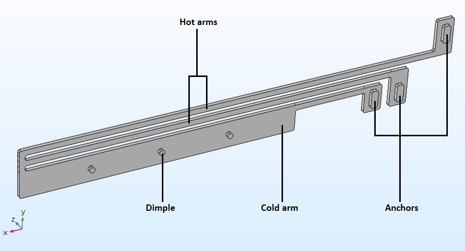
Model geometry of the three-arm thermal microactuator.
To model the electrical currents, heat generation, and deformation, you can use the Joule Heating and Thermal Expansion multiphysics interface. This feature automatically adds (and couples) the equations for the three physics, making it simple to simulate how the voltage produces an electric current that in turn generates heat. The heat induces thermal expansion, which, if the actuator is restrained, can lead to deformation.
The microactuator is made up of polysilicon, which is commonly used for thermal microactuators due to its easy integration with electronic components. In the real world, as currents flow through a material and increase its temperature, it becomes more resistant to the electricity. For simplicity’s sake, though, this model assumes that the material properties remain constant (a one-way coupling). If you wanted to turn this into a two-way coupling, you would just need to use a material with a temperature-dependent electrical conductivity.
Evaluating the Simulation Results
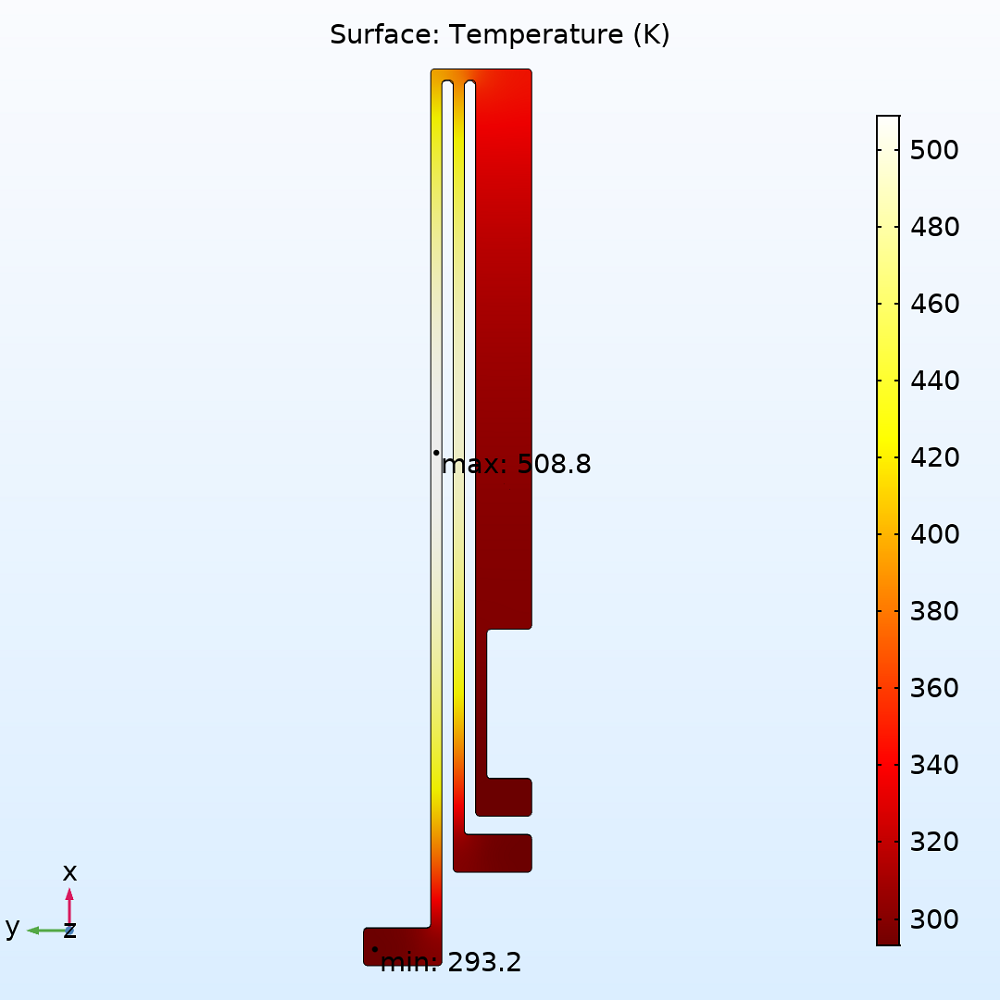
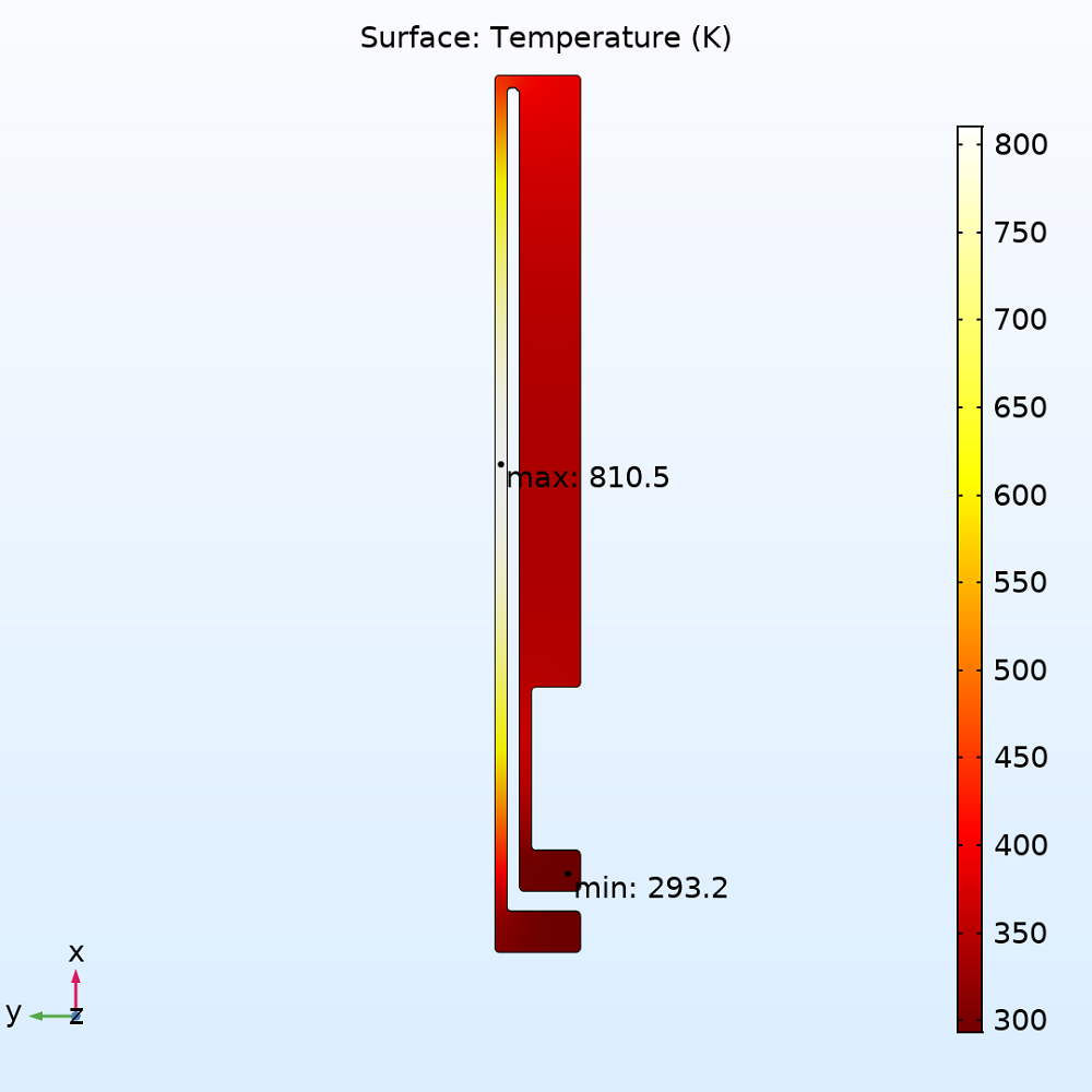
By performing a stationary simulation, you can determine the amount of displacement in the actuator due to thermal expansion, based on the temperature rise in the device, or visualize and find the maximum electric current and voltage. You can also calculate the maximum and minimum temperatures reached in the three-arm microactuator, as shown in the left image below. You can then alter the design to optimize the temperature increase for the intended use by, for instance, adjusting the voltage. In addition, you could modify the geometry, as shown in the images below, which compare the maximum and minimum temperatures in a three-arm microactuator design to a version with two arms.
Max temperatures in the three-arm (left) and two-arm (right) thermal microactuators.
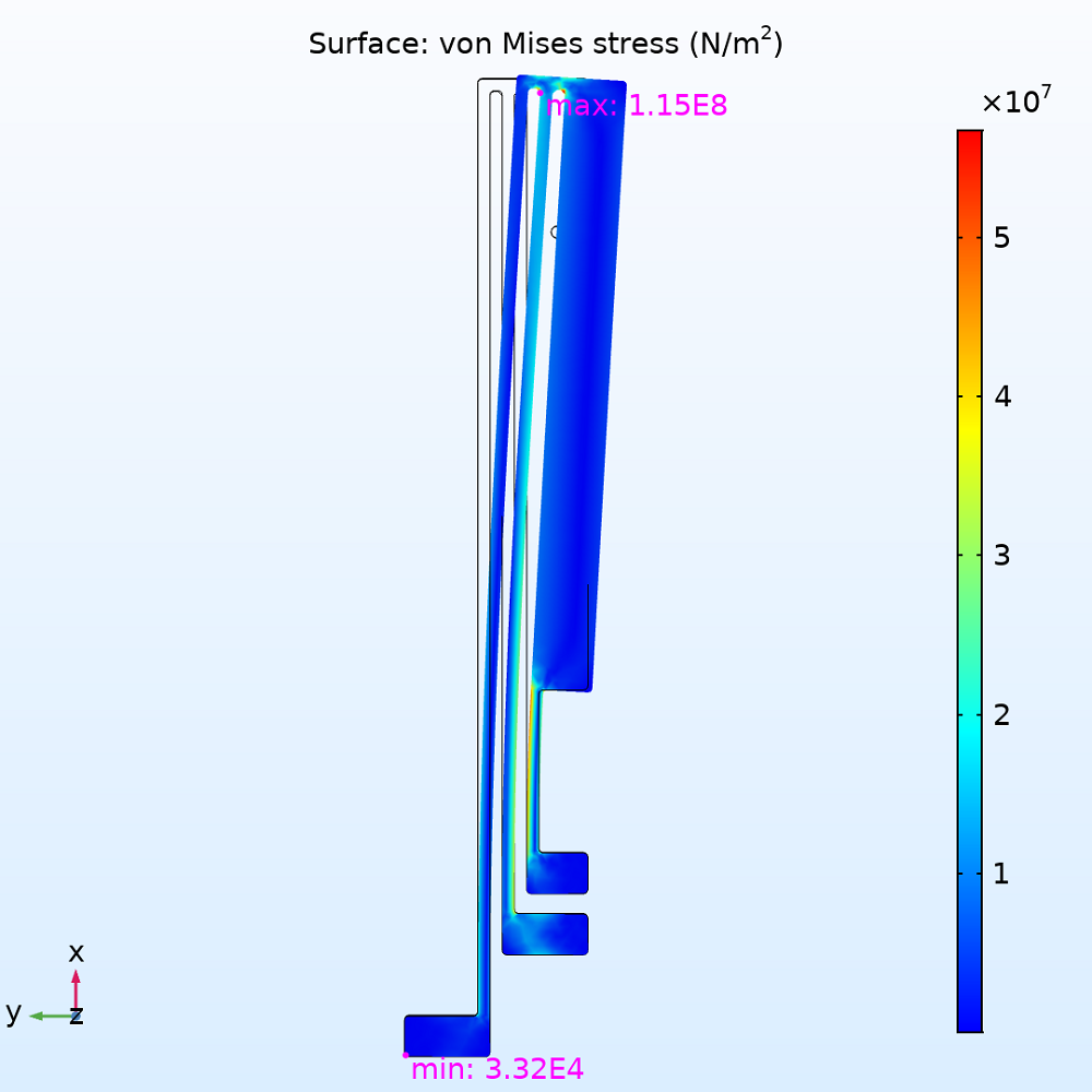
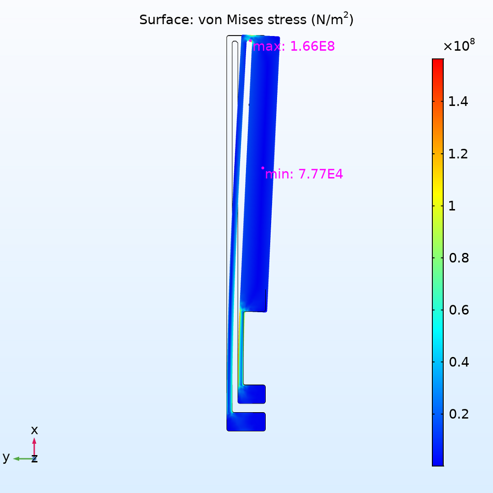
In addition, you can determine the amount of displacement in the actuator and predict the resulting stress. As shown in the images below, you can even predict the displacement at different points in the actuator.
Von Mises stress in the three-arm (left) and two-arm (right) microactuators, showing the total amount of displacement.
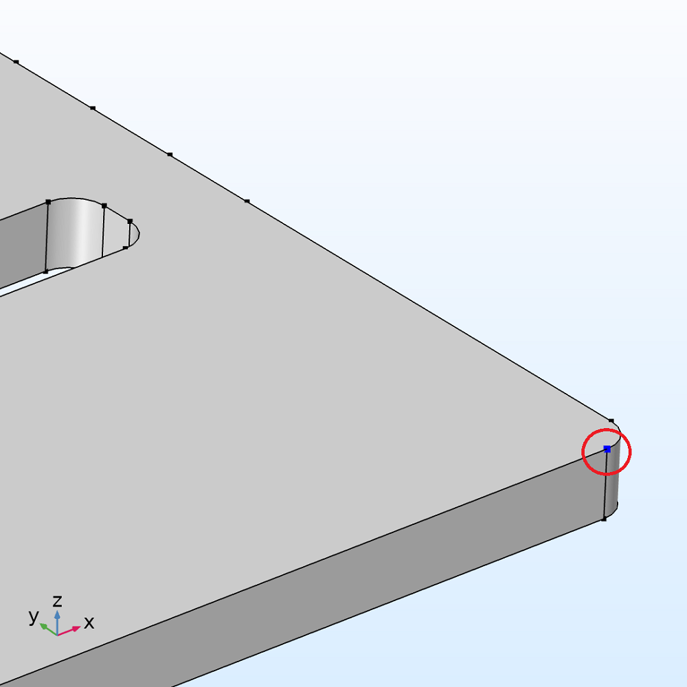
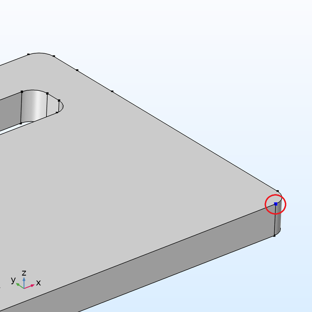
Outer (top) and lower (bottom) tips for the three-arm (left) and two-arm (right) microactuator designs, where the displacement is measured from.
Alternatively, you can view the total displacement and maximum (and minimum if you prefer) temperature together, which makes it easy to compare the MEMS designs. Using the results, you can choose the design that works better for your specific use case and then optimize it.


Tables displaying the total displacement at the outer (top) and lower (inner) tips of the actuators, as well as the maximum temperature observed for each design.
Next Steps
Want to try modeling a thermal microactuator? Click the button below to go to the Application Gallery. You’ll find step-by-step documentation for this model as well as an MPH file.
This example actually exists in several different “flavors”:
- Thermal Actuator
- The example described here
- Requires the Structural Mechanics Module or the MEMS Module
- Thermal Actuator – Parameterized
- The same model as above, but the geometry is parameterized so that it is easy to create variants of the geometry
- Joule Heating of a Microactuator
- Only the heating part is modeled
- Does not require any add-on licenses
- Joule Heating of a Microactuator – Distributed Parameter Version
- The same model as above, but it also shows how to distribute several parameter values on a cluster
- Requires a floating network license
- Thermal Microactuator Simplified
- Thermal expansion is included by editing the equations in Equation View rather than by using a multiphysics coupling
- Does not require any add-on licenses




Comments (0)